
Apparatus for analyzing sample

a sample and apparatus technology, applied in the field of apparatus for analyzing samples, can solve the problems of small sample quantity contaminating the interior elements of the sample testing apparatus, the sample is stuck around the inlet hole, and the sample is contaminated

Active Publication Date: 2011-07-21
PRECISIONBIOSENSOR INC
View PDF6 Cites 20 Cited by
  • Summary
  • Abstract
  • Description
  • Claims
  • Application Information

AI Technical Summary

Benefits of technology

[0013]One or more exemplary embodiments provide a microfluidic device which is driven based on centrifugal force and prevents a sample from being stuck to a surface of the apparatus for analyzing sample in the course of being injected into the apparatus for analyzing sample.
[0014]One or more exemplary embodiments also provide a apparatus for analyzing sample based on centrifugal force to prevent, e.g., interior elements of a sample testing apparatus from being contaminated by a sample stuck to the apparatus for analyzing sample during rotation of the apparatus for analyzing sample.
[0015]In accordance with an aspect of an exemplary embodiment, there is provided a apparatus for analyzing sample including a platform having a disk shape, in which chambers and channels are defined, the platform including a sample inlet hole formed in an outer surface of the platform to inject the sample into the platform, an opening to introduce a residual sample into a receiving space isolated from the chambers and channels defined in the platform, and a barrier surrounding the opening to prevent the residual sample from moving in a radial outward direction of the platform.
[0018]The apparatus for analyzing sample may further include a protruding portion surrounding the sample inlet hole to prevent overflow of the residual sample.
[0023]In accordance with an aspect of another exemplary embodiment, there is provided a apparatus for analyzing sample including a platform having a disk shape, the platform including a sample inlet hole to inject the sample into the platform, a residual sample receptacle provided at a radially outward position of the sample inlet hole, and a barrier to prevent a residual sample to be introduced into the residual sample receptacle from moving outward from the residual sample receptacle.

Problems solved by technology

However, injecting the sample using a pipet or syringe may cause the sample to be stuck around the inlet hole.
The sample, especially a biological sample, stuck around the inlet hole may contaminate a surface of the apparatus for analyzing sample.
In addition, if the microfluidic device containing the sample is mounted in a sample testing apparatus, a small quantity of the sample may contaminate interior elements of the sample testing apparatus, such as a light source, etc., during rotation of the microfluidic device.
If the sample is stuck to the light source or an outer surface of a testing chamber, this may cause an error in results of the microfluidic device.
In addition, if a sample containing disease-causing agents is injected into the apparatus for analyzing sample, a residual sample on the surface of the microfluidic device may cause secondary infection.

Method used


Image

  • Apparatus for analyzing sample
  • Apparatus for analyzing sample
  • Apparatus for analyzing sample

Examples


Embodiment Construction

[0039]Reference will now be made in detail to a apparatus for analyzing sample and a sample testing apparatus using the same according to exemplary embodiments, examples of which are illustrated in the accompanying drawings, wherein like reference numerals refer to like elements throughout.

[0040]In the drawings, structures, such as chambers, channels, etc., may be illustrated in simplified shapes, and may be magnified or reduced differently from an actual size ratio thereof. In the terms, such as, e.g., “apparatus for analyzing sample” and “micro-particle”, “micro-” is used only in contrast to “macro-”, and should not be interpreted as being limited to any specific size.

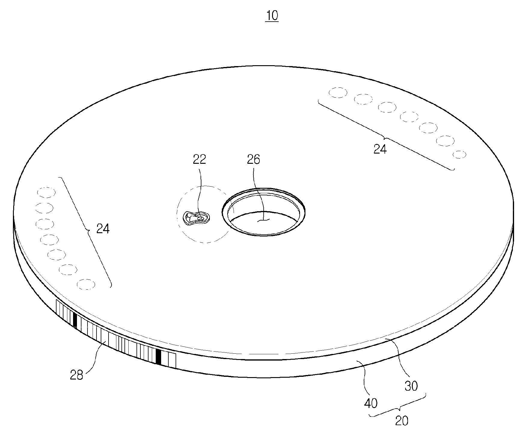
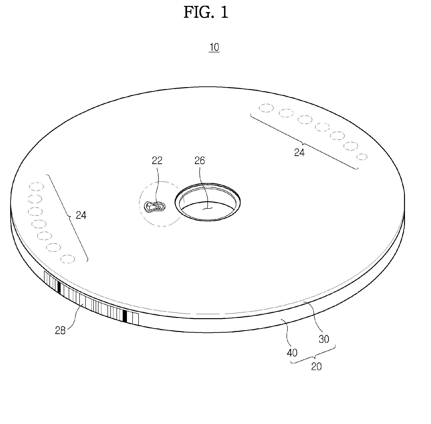
[0041]FIG. 1 is a perspective view illustrating a apparatus for analyzing sample according to an exemplary embodiment.

[0042]Referring to FIG. 1, the apparatus for analyzing sample 10 includes a rotatable disk-shaped platform 20.

[0043]The platform 20 may be made of plastics which are easy to mold and have biologically...


PUM


Abstract

A apparatus for analyzing sample to prevent a sample from being stuck to a surface of the apparatus for analyzing sample in the course of being injected into the apparatus for analyzing sample. The apparatus for analyzing sample includes a platform having a disk shape. The platform includes chambers and channels, a sample inlet hole which is formed in an outer surface the platform and through which a sample is injected into the platform; an opening which is formed in the outer surface of the platform and through which a residual of the sample, present on the outer surface of the platform around the sample inlet hole, is introduced into a receiving space isolated from the chambers and channels; and a barrier which is formed on the outer surface of the platform around a portion of the opening to prevent the residual of the sample from moving past the opening in a radial outward direction of the platform.

Description

CROSS-REFERENCE TO RELATED APPLICATION[0001]This application claims priority from Korean Patent Application No. 10-2010-0004092, filed on Jan. 15, 2010 in the Korean Intellectual Property Office, the disclosure of which is incorporated herein by reference.BACKGROUND[0002]1. Field[0003]Apparatuses consistent with exemplary embodiments relate to a apparatus for analyzing sample to perform a biochemical process on a sample.[0004]2. Description of the Related Art[0005]Generally, a device used to implement a biological or chemical reaction using a small quantity of fluid is referred to as apparatus for analyzing sample. Such a apparatus for analyzing sample includes microfluidic structures arranged in a platform that may have various shapes, e.g., chip and disk shapes.[0006]Microfluidic structures include a chamber which contains a fluid, a channel for fluid flow, and a valve to control the fluid flow. The chamber, channel and valve may be arranged according to various configurations wit...

Claims


Application Information

Patent Timeline
IPC IPC(8): G01N33/48
CPCB01L3/502738B01L3/502746B01L2200/0642B01L2200/141B01L2400/086B01L2300/022B01L2300/0803B01L2400/0409B01L2300/021B04B5/02G01N21/00G01N21/27G01N35/00G01N35/08
Inventor KIM, HYUN MINKIM, DO GYOONPARK, JONG MYEON
Owner PRECISIONBIOSENSOR INC
Learn More