Balancing valve in faucet

a technology of balancing valve and faucet, which is applied in the direction of mechanical equipment, functional valve types, transportation and packaging, etc., can solve the problems of user burns, hot water may change the temperature of the water, and hot water may burn the user, so as to reduce the size, increase the safety of use, and facilitate cleaning and replacement

Inactive Publication Date: 2013-08-08
SHANGHAI GEAR PLASTIC
View PDF5 Cites 16 Cited by
  • Summary
  • Abstract
  • Description
  • Claims
  • Application Information

AI Technical Summary

Benefits of technology

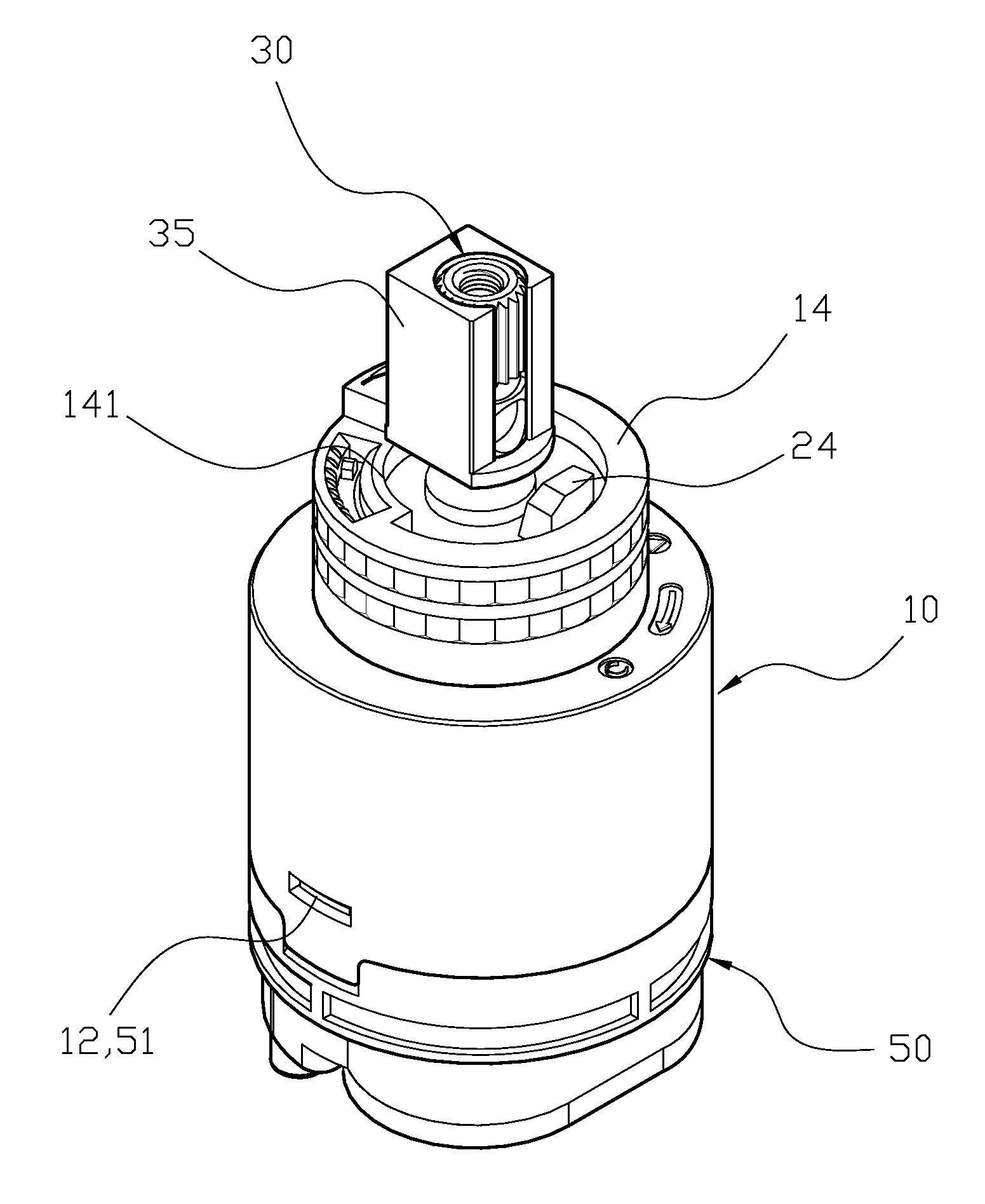
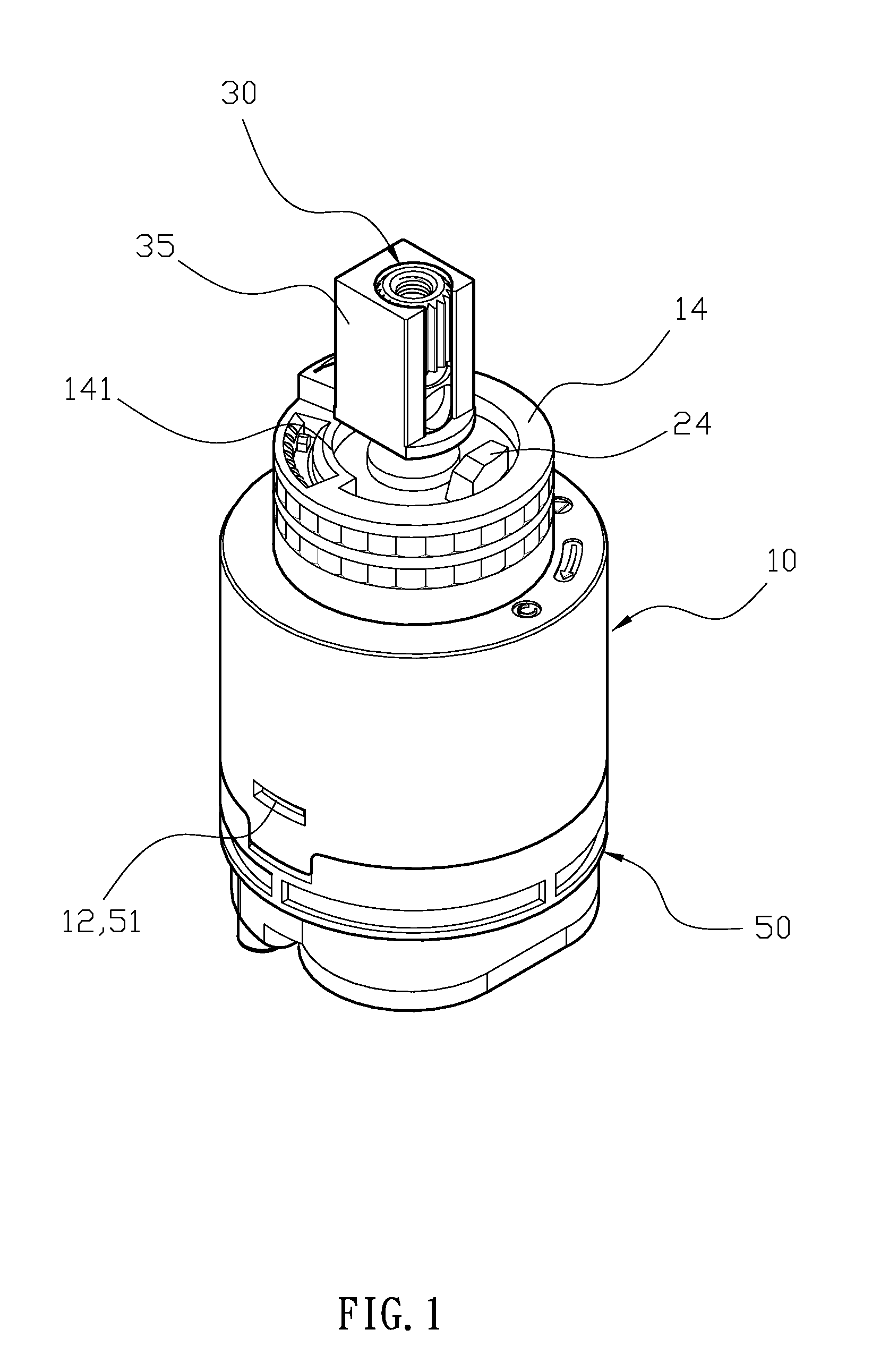
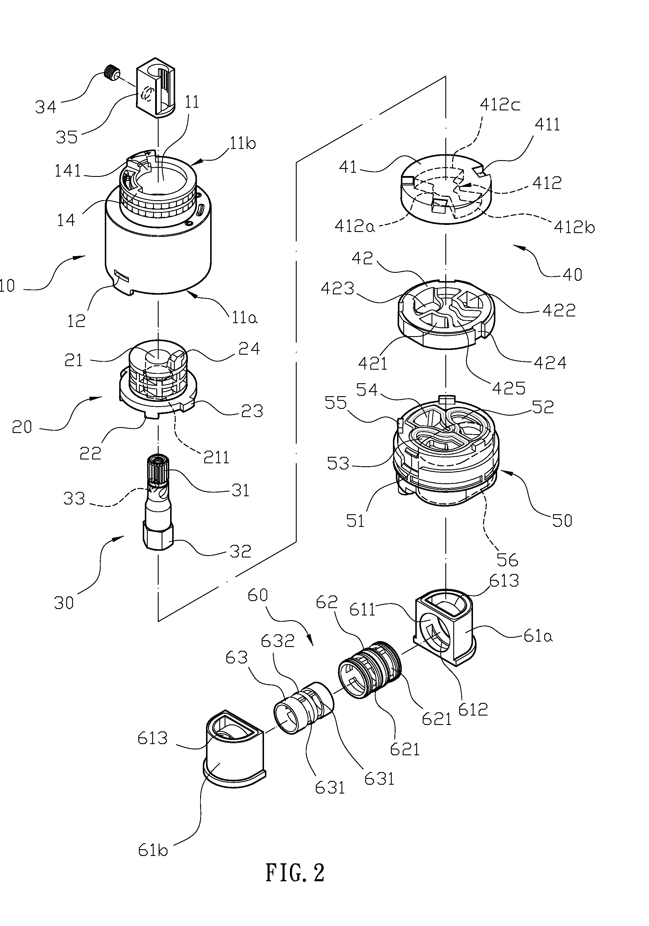
[0004]It is a main objective of the present invention that when the imbalance of the cold and hot water pressure results, the moving valve of the balancing valve set is slidingly disposed in the valve cover to push the stopping wall of the moving valve by the cold and hot water pressure, and the moving valve slightly slides towards the end with smaller water pressure. So, the flow restricting openings of the moving valve block different amount of water from the water-guiding slots to adjust the amount of water from therefrom to achieve the goal of automatically adjusting the flow of the cold and hot water by the change of water pressure. It can further achieve the goal of maintaining water output temperature to increase the safety when in use.
[0005]It is another objective of the present invention that the balancing valve set is disposed at the receiving chamber of the valve base from outside, so when a user wants to clean or replace it, the balancing valve set can be taken out directly from the valve base without disassembling the valve shell and valve base to further achieve the goal of easy cleaning and replacement. Also, the size is reduced since the balancing valve set is disposed in the receiving chamber of the valve base, so that it can be used for conventional faucets.
[0006]It is a further objective of the present invention that when the connecting cover rotates axially, the extending portion is blocked and restricted by the restricting portion of the valve shell to control a rotating angle of the connecting cover. Furthermore, the collecting trough of the first vale piece has a circular portion that extends to form a first fan-shaped portion and a second fan-shaped portion, and a mixing trough is formed and connected with the water outlet closely attaching to the first valve piece. The mixing trough extends toward a location between the hot water inlet and the cold water inlet, and when the first fan-shaped portion and second fan-shaped portion are aligned with the mixing trough, the ceramic valve set shuts off and no water is outputted. When the first valve piece starts to rotate, the first fan-shaped portion of the collecting trough overlaps the cold water inlet of the second valve piece, and if the first valve piece further rotates, the second fan-shaped portion overlaps the hot water inlet of the second valve piece. So, whenever the faucet is in use, the cold water will always come out first and then the warm or hot water to avoid the accident of burning.

Problems solved by technology

However, the design of an outer shell of the conventional faucet only has a space to receive the control valve and there is no additional space for a balancing valve.
So, when a user wants to install the balancing valve to maintain the water temperature, the entire outer shell of the faucet has to be replaced, which will cause inconvenience during assembly / disassembly process and waste of the materials.
If there is no balancing valve and the water flow is divided when in use, the water pressure of the cold and hot water may be imbalanced to generate unstable water flow, and may cause the sudden temperature change of the water.
More seriously, the unexpected hot water may burn the user.
In this setting, it is disadvantageous that the user may mistakenly rotate the handle to the hot water end to release the entire hot water, and the user may be burned by the hot water.

Method used


Image

  • Balancing valve in faucet
  • Balancing valve in faucet
  • Balancing valve in faucet

Examples


Embodiment Construction

[0019]The detailed description set forth below is intended as a description of the presently exemplary device provided in accordance with aspects of the present invention and is not intended to represent the only forms in which the present invention may be prepared or utilized. It is to be understood, rather, that the same or equivalent functions and components may be accomplished by different embodiments that are also intended to be encompassed within the spirit and scope of the invention.

[0020]Unless defined otherwise, all technical and scientific terms used herein have the same meaning as commonly understood to one of ordinary skill in the art to which this invention belongs. Although any methods, devices and materials similar or equivalent to those described can be used in the practice or testing of the invention, the exemplary methods, devices and materials are now described.

[0021]All publications mentioned are incorporated by reference for the purpose of describing and disclos...


PUM


Abstract

A balancing faucet in a faucet includes a valve shell, a connecting cover, a rotating shaft, a ceramic valve set, a valve base and a balancing valve set. The ceramic valve set has a first valve piece and a second valve piece attaching to each other, and a collecting trough is formed at the direction from the first valve piece to the second valve piece, and the second valve piece has a hot water inlet, a cold water inlet and a water outlet. The valve base has a receiving chamber to receive the balancing valve set formed by two symmetric engaging shells to provide a valve-shaft hole for a valve cover. The valve cover has two water-guiding slots and a moving valve that has two flow restricting openings and a stopping wall to automatically adjust the flow of cold and hot water to further maintain the water temperature.

Description

FIELD OF THE INVENTION[0001]The present invention relates to a balancing valve in a faucet, and more specifically to a balancing valve in a faucet that can automatically adjust water flow using the change of water pressure.BACKGROUND OF THE INVENTION[0002]A conventional faucet usually has a control valve inside, and the control valve is used for water outputting. However, the design of an outer shell of the conventional faucet only has a space to receive the control valve and there is no additional space for a balancing valve. So, when a user wants to install the balancing valve to maintain the water temperature, the entire outer shell of the faucet has to be replaced, which will cause inconvenience during assembly / disassembly process and waste of the materials. If there is no balancing valve and the water flow is divided when in use, the water pressure of the cold and hot water may be imbalanced to generate unstable water flow, and may cause the sudden temperature change of the wat...

Claims


Application Information

Patent Timeline
Patent Type & Authority Applications(United States)
IPC IPC(8): F16K17/00
CPCF16K11/0743F16K11/044Y10T137/7837
Inventor LAW, CHUNG-HSING
Owner SHANGHAI GEAR PLASTIC
Why Eureka
Try Eureka