Adjustable tool support clamp

a tool support and adjustable technology, applied in the field of clamps, can solve the problems of exposing the metal hooks, the soft pads of the gripping hooks tend to wear, and the hooks can scratch or otherwise damage the vehicle body, so as to achieve the effect of enhancing versatility and structural adaptability

Active Publication Date: 2013-08-08
SNAP ON INC
View PDF9 Cites 13 Cited by
  • Summary
  • Abstract
  • Description
  • Claims
  • Application Information

AI Technical Summary

Benefits of technology

[0007]The clamp disclosed in the present application provides additional advantages to conventional support clamps by adding versatility and structural adaptability to the support clamp. The present application discloses an adjustable tool support clamp having a tension member enclosed by a tubular body. The tension member is coupled to the inside of the tubular body at a first end, and to a rod at an opposing second end. Removable grips may be coupled to the ends of the tubular body, but are preferably not directly coupled to the tension member. The grips can be pivotable to accommodate a variety of different gripping surfaces.

Problems solved by technology

However, the soft pads of the gripping hooks tend to wear after use, exposing the metal hooks underneath.
The metal hooks can then scratch or otherwise damage the vehicle body without the protection of the soft pads.
The gripping hooks are typically under tension, making them difficult to replace.
If the user were to accidentally release the tension member, it would retract inside the tube and be difficult to retrieve.
Conventional clamps are somewhat generic in design to fit over the largest hood flange, but in turn, are unstable when gripping narrower flanges.
The generic design of the conventional clamp causes the clamp to have difficulty gripping the many different flange designs and, in some cases, the clamp can slip and cause damage when attached to a tapered flange.
Also, conventional gripping hooks are rigid or rotatable in only one direction, making it difficult to adequately grip many surfaces unless the gripping hooks are perfectly aligned.
Conventional clamps also lack versatility in that they are designed to hold only one specific type of device in place, typically a long tubular light similar to a fluorescent light bulb.
The conventional support clamp is generally not well suited to provide concentrated light to these specific areas.

Method used


Image

  • Adjustable tool support clamp
  • Adjustable tool support clamp
  • Adjustable tool support clamp

Examples


Embodiment Construction

[0020]While the present invention is susceptible of embodiments in many different forms, there is shown in the drawings and will herein be described in detail a preferred embodiment of the invention with the understanding that the present disclosure is to be considered as an exemplification of the principles of the invention and is not intended to limit the broad aspect of the invention to embodiments illustrated.

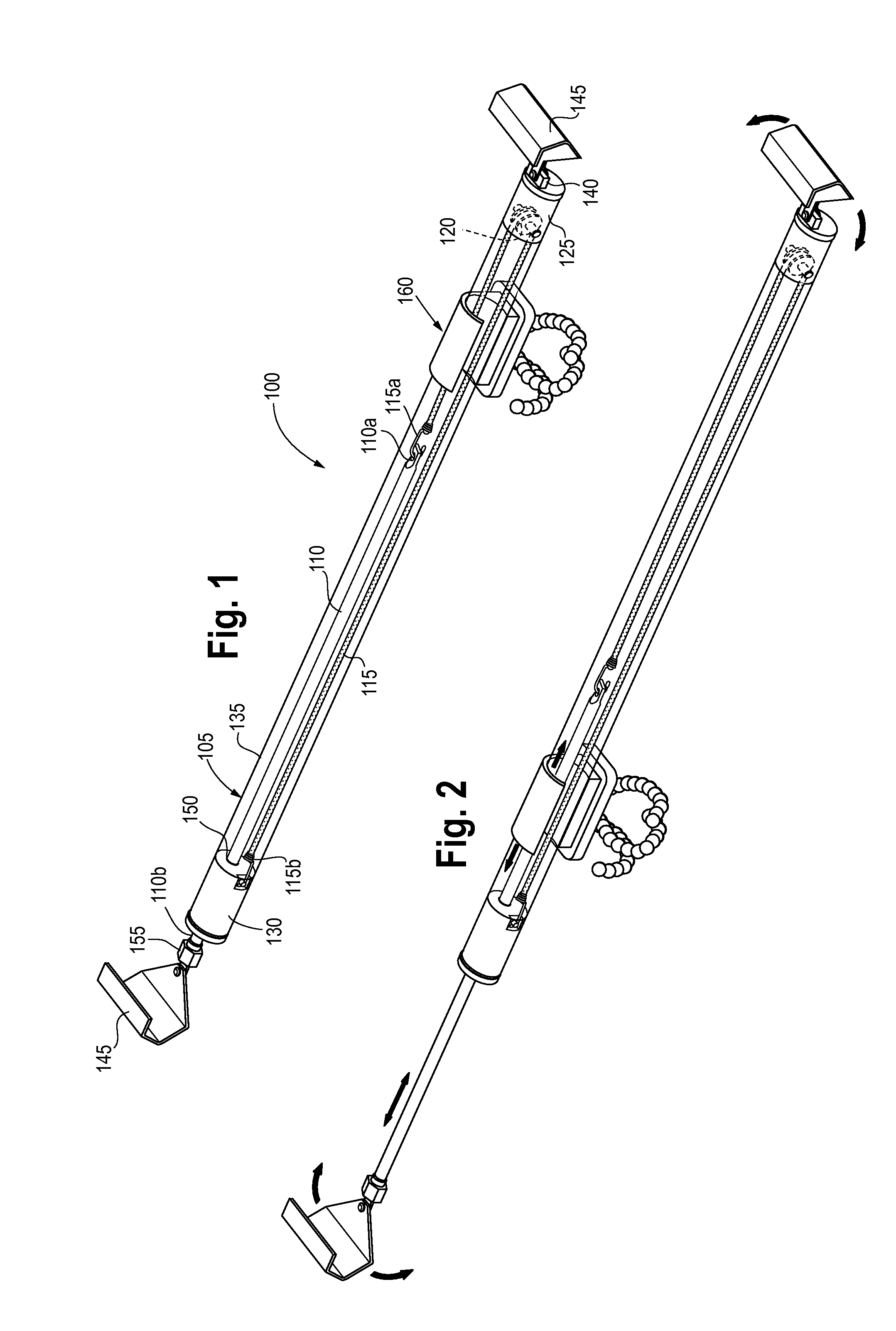
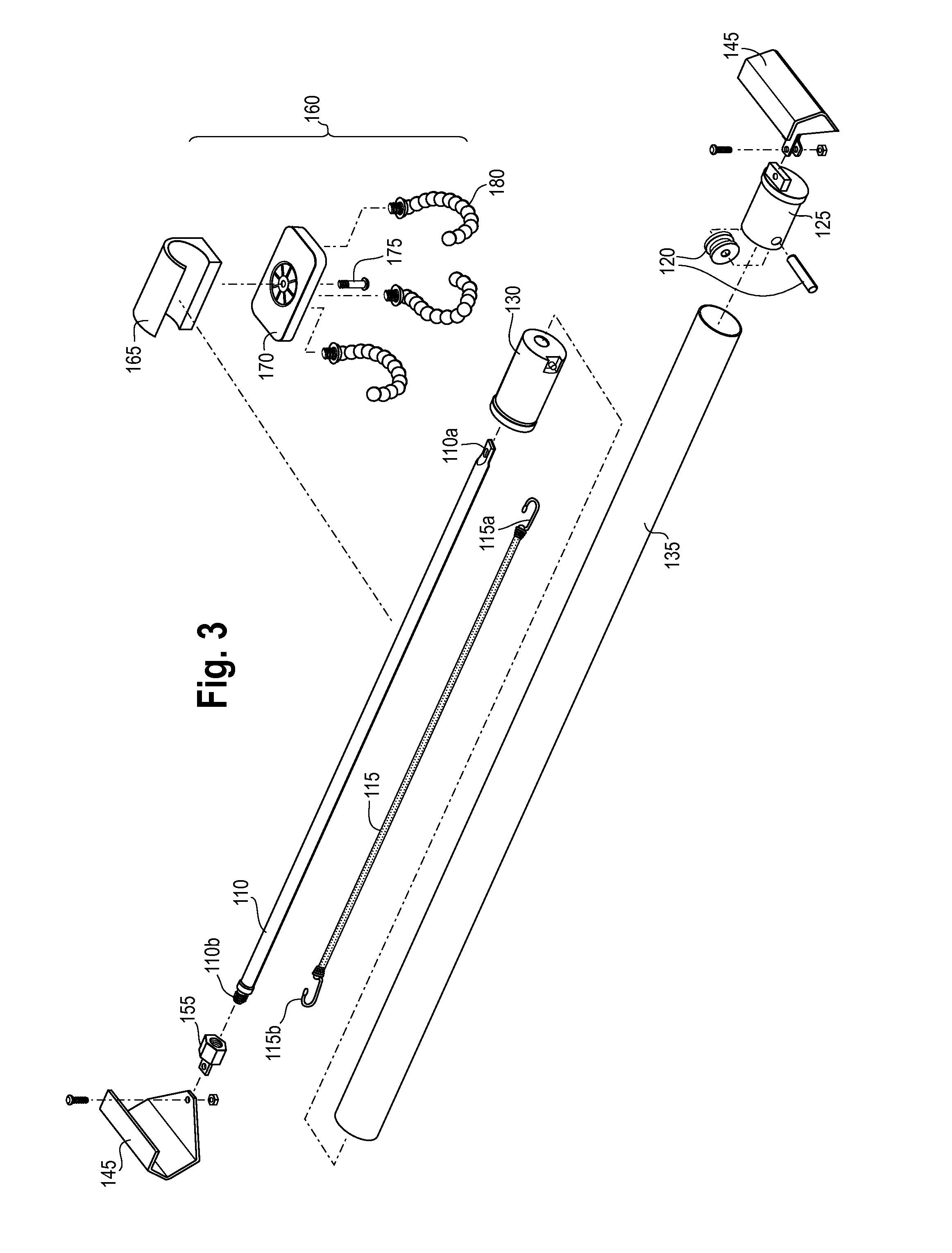
[0021]The clamp structures disclosed herein provide versatility and structural adaptability to support clamps. The clamp can include a tension member that is coupled to an inside of a tubular body at a first end and to a rod at an opposing second end. In an embodiment, removable grips may be coupled to the ends of the tubular body but are preferably not directly coupled to the tension member so that replacing or changing the grips can be done without removing the tension member from its anchored position. The grips can, in some embodiments, be pivotable to accommodate a var...


PUM


Abstract

A clamp structure that provides versatility and structural adaptability to different clamping surfaces. A tension member can be coupled to the inside of a tubular body at one end and to a rod at the other end. Removable grips can be coupled to the ends of the body, but are not directly coupled to the tension member so that changing the grips can be done without removing the tension member from its anchored position. The grips can, in some embodiments, be pivotable so as to accommodate a variety of different gripping surfaces. Various holding members such as a tool holder, a utility hook and/or a claw grip can be movably provided on the body and can hold tools or light fixtures in a variety of configurations.

Description

FIELD OF THE INVENTION[0001]The present application relates generally to clamps. More particularly, the present application relates to an adjustable tool support clamp having a removable gripping mechanism and tension member configuration.BACKGROUND OF THE INVENTION[0002]Adjustable support clamps are commonly used in the automotive industry to hold objects under the hood of the automobile when performing repairs or other tasks. Conventional support clamps typically include hooks that engage lateral edges of an automobile hood and position a light to illuminate the working space. Typically, soft rubber, plastic or non-marring pads are disposed over the hooks of the support clamps to protect the vehicle paint or metal from being damaged. However, the soft pads of the gripping hooks tend to wear after use, exposing the metal hooks underneath. The metal hooks can then scratch or otherwise damage the vehicle body without the protection of the soft pads.[0003]The gripping hooks are typica...

Claims


Application Information

Patent Timeline
Patent Type & Authority Applications(United States)
IPC IPC(8): F16M13/00
CPCF16M11/041F16M13/00F21V21/13F16M13/022B25H5/00
Inventor WOLLERT, GARY S.
Owner SNAP ON INC
Why Eureka
Try Eureka