Ultrasonic Touch Sensor With A Display Monitor

a touch sensor and display monitor technology, applied in the field of ultrasonic touch sensors with display monitors, can solve the problems of failure in dirty, wet or adverse conditions, and devices without built-in capabilities

Active Publication Date: 2013-08-08
QUALCOMM INC
View PDF4 Cites 119 Cited by
  • Summary
  • Abstract
  • Description
  • Claims
  • Application Information

AI Technical Summary

Benefits of technology

[0007]The display monitor may he comprised of layers of components, and the ultrasonic device may be comp...

Problems solved by technology

Although these prior art touch screen monitors have become reliable and inexpensive, the prior art devices do not incorporate any built-in sensing elements suitable fo...

Method used


Image

  • Ultrasonic Touch Sensor With A Display Monitor
  • Ultrasonic Touch Sensor With A Display Monitor
  • Ultrasonic Touch Sensor With A Display Monitor

Examples


Embodiment Construction

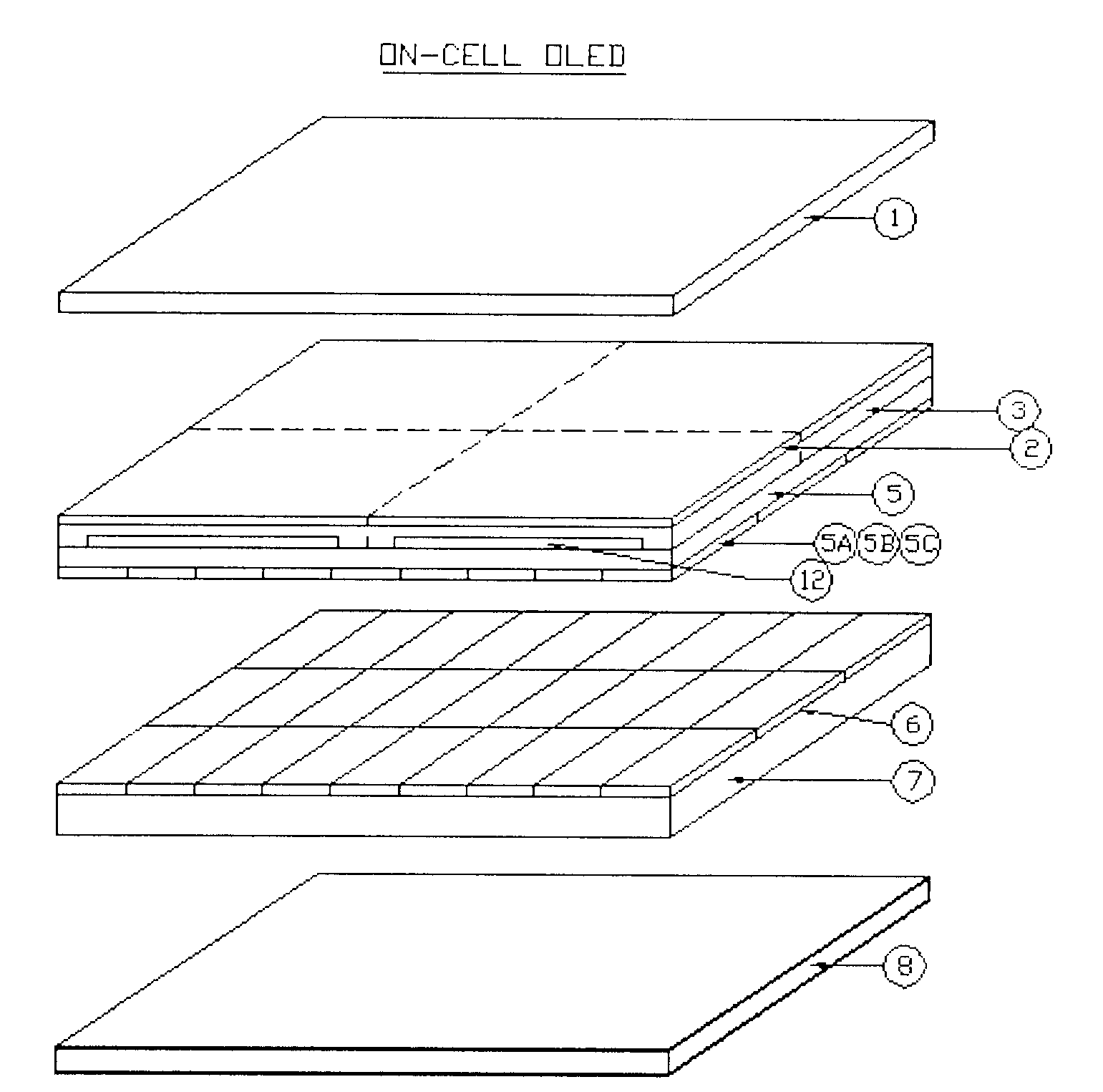
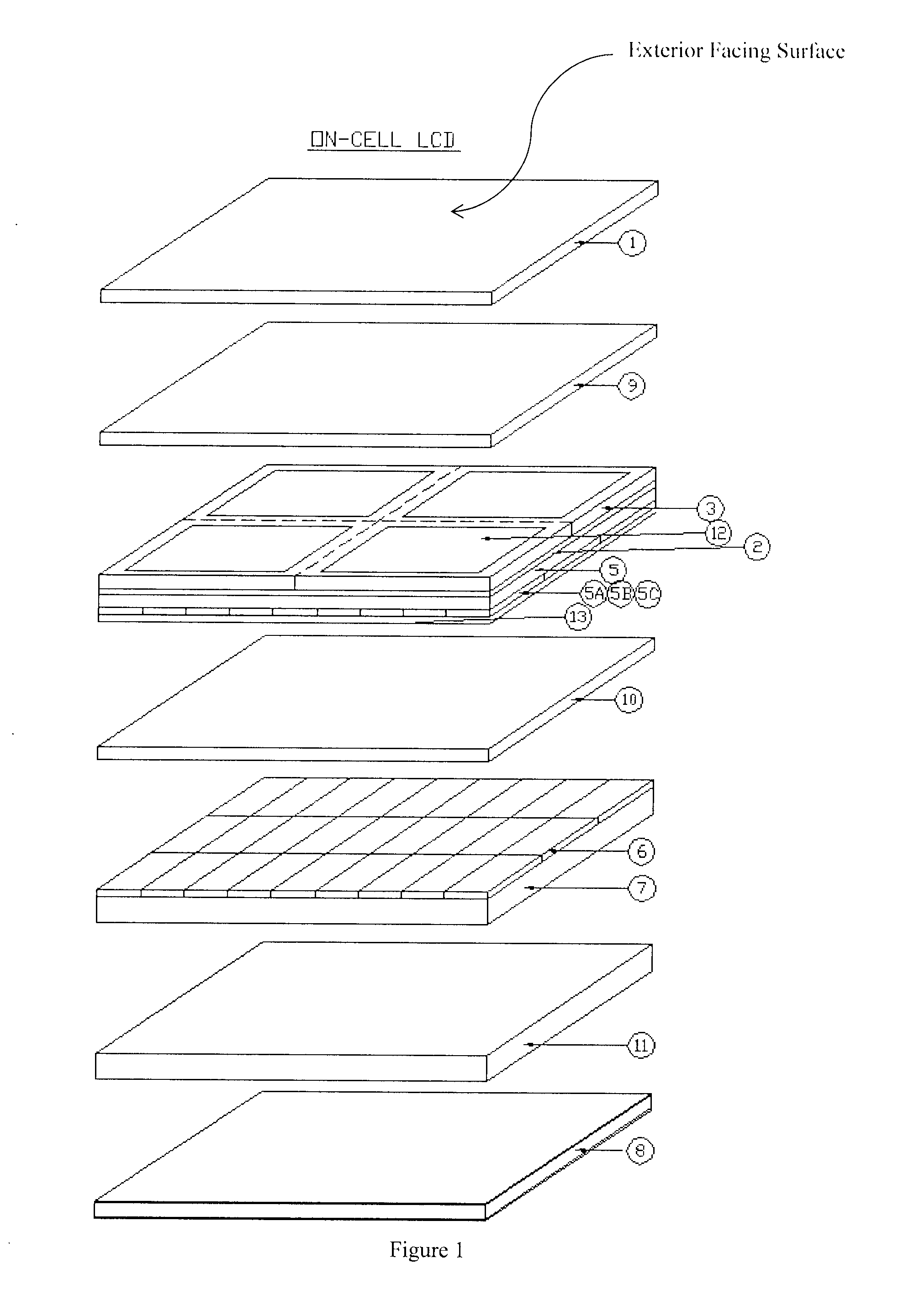
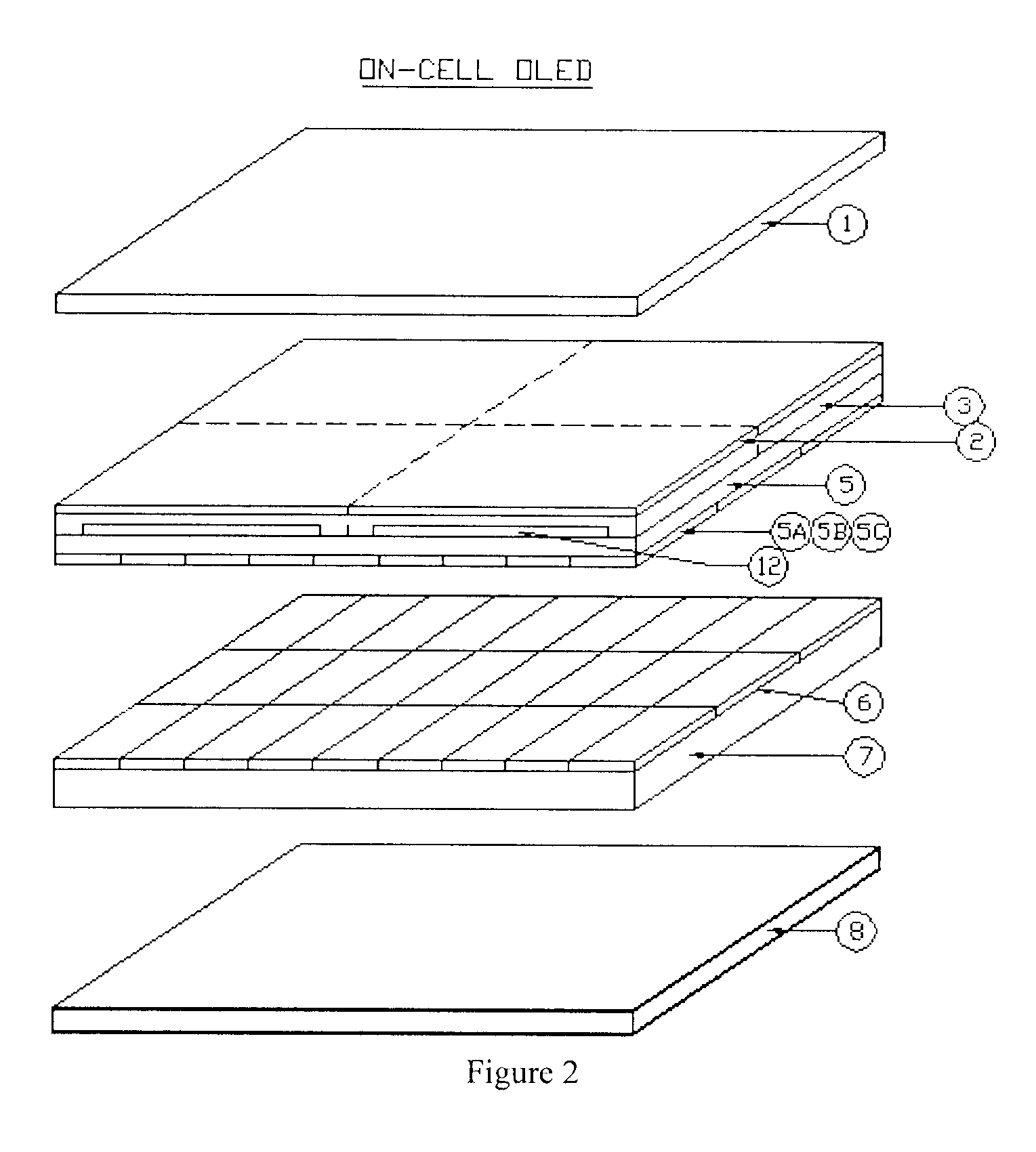
[0028]The present invention relates to ultrasonic scanning devices and display monitors. Information about an object that is in contact with the display monitor is gathered by means of ultrasonic energy. Ultrasonic energy is sent toward a surface of the display monitor where a pointing object may contact the display monitor. When the ultrasonic energy reaches the pointing object, at least some of the ultrasonic energy is reflected toward an ultrasonic energy receiver. The receiver detects the reflected energy, transmits a signal indicating that reflected energy was sensed. Using the transmitted signal, information about the object is determined. That information may include one or more of the following: (a) the location of the pointing object, (b) information about the texture of the surface of the pointing object, and / or information about the structure of features present in the pointing object, but which are not on the surface of the pointing object.

[0029]In one embodiment of the ...


PUM


Abstract

A touch screen monitor having a display monitor and an ultrasonic device. The ultrasonic device may include a sensor array using piezoelectric sensors to detect the surface topology of a biological or other object that is in contact with a surface of the display monitor. The display monitor may be a LCD or LED monitor.

Description

CROSS-REFERENCE TO RELATED APPLICATION [0001]This application claims the benefit of priority to U.S. provisional patent application Ser. No. 61 / 594,330, filed on Feb. 2, 2012.FIELD OF THE INVENTION [0002]The present invention relates to devices and methods of collecting information about an object that is in contact with a display.BACKGROUND OF THE INVENTION[0003]In the prior art, touch screen monitors are commonly used to assist users with selecting items displayed on a monitor. Selecting items is commonly performed using a pointing object, such as a stylus or a finger. Such touch screen monitors often employ a capacitance sensor to identify the location at which the pointing object touches the display monitor. The identified location is then compared to the location of images displayed on the monitor in order to determine what the user is identifying.[0004]Although these prior art touch screen monitors have become reliable and inexpensive, the prior art devices do not incorporate ...

Claims


Application Information

Patent Timeline
IPC IPC(8): G06F3/041
CPCG06F3/041G06F3/043G06F3/0412
Inventor SCHNEIDER, JOHN K.KITCHENS, JACK C.
Owner QUALCOMM INC
Why Eureka
Try Eureka