Display device

Active Publication Date: 2013-08-15
SHARP KK
View PDF4 Cites 0 Cited by
  • Summary
  • Abstract
  • Description
  • Claims
  • Application Information

AI Technical Summary

Benefits of technology

The invention aims to improve the display device by reducing the likelihood of display defects and reducing the size of the frame section.

Problems solved by technology

In such a display device, unevenness in a displayed image may largely deteriorate an image quality.
The unevenness includes brightness unevenness that may be caused by display brightness varied for each pixel and color unevenness that may be caused by chromaticity difference.
In addition to such unevenness, problems of unevenness caused by a dependence of gamma characteristics, which is varied according to a gradation level of the display brightness, on a visual perception are increasing.

Method used


Image

  • Display device
  • Display device
  • Display device

Examples


first embodiment

[0044]A first embodiment of the present invention will be described with reference to the drawings.

[0045]1. Configuration of a Display Device

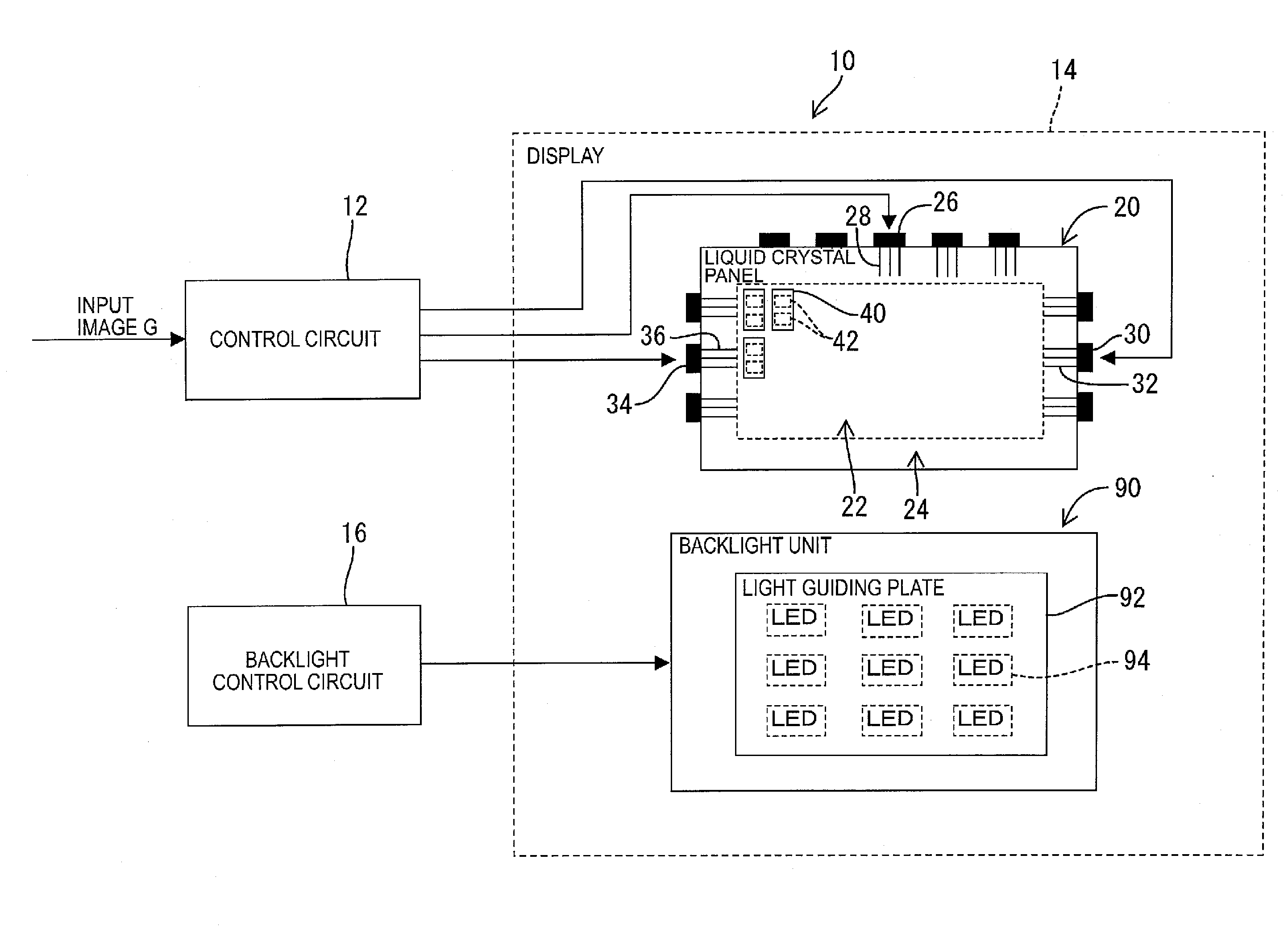
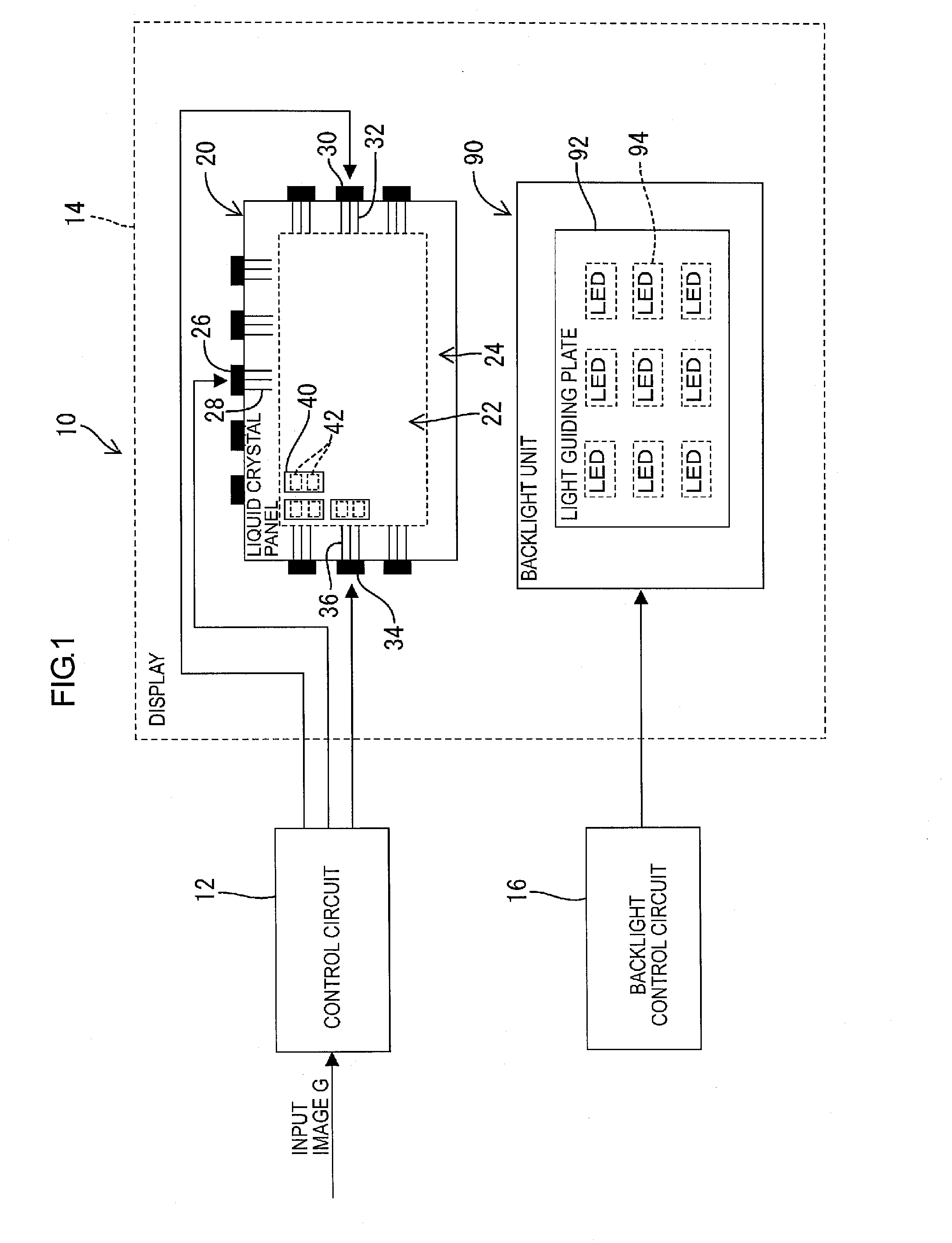
[0046]As illustrated in FIG. 1, a display device 10 includes a control circuit 12, a display section 14, and a backlight control circuit 16. The display section 14 includes a liquid crystal panel 20 and a backlight unit 90.

[0047]The control circuit 12 is configured to drive the liquid crystal panel 20 based on an input image G supplied from an external device (not illustrated). The backlight control circuit 16 is configured to drive the backlight unit 90. The backlight control unit 16 may be configured to drive the backlight unit 90 in conjunction with the control circuit 12 or to drive the backlight unit 90 independently from the control circuit 12.

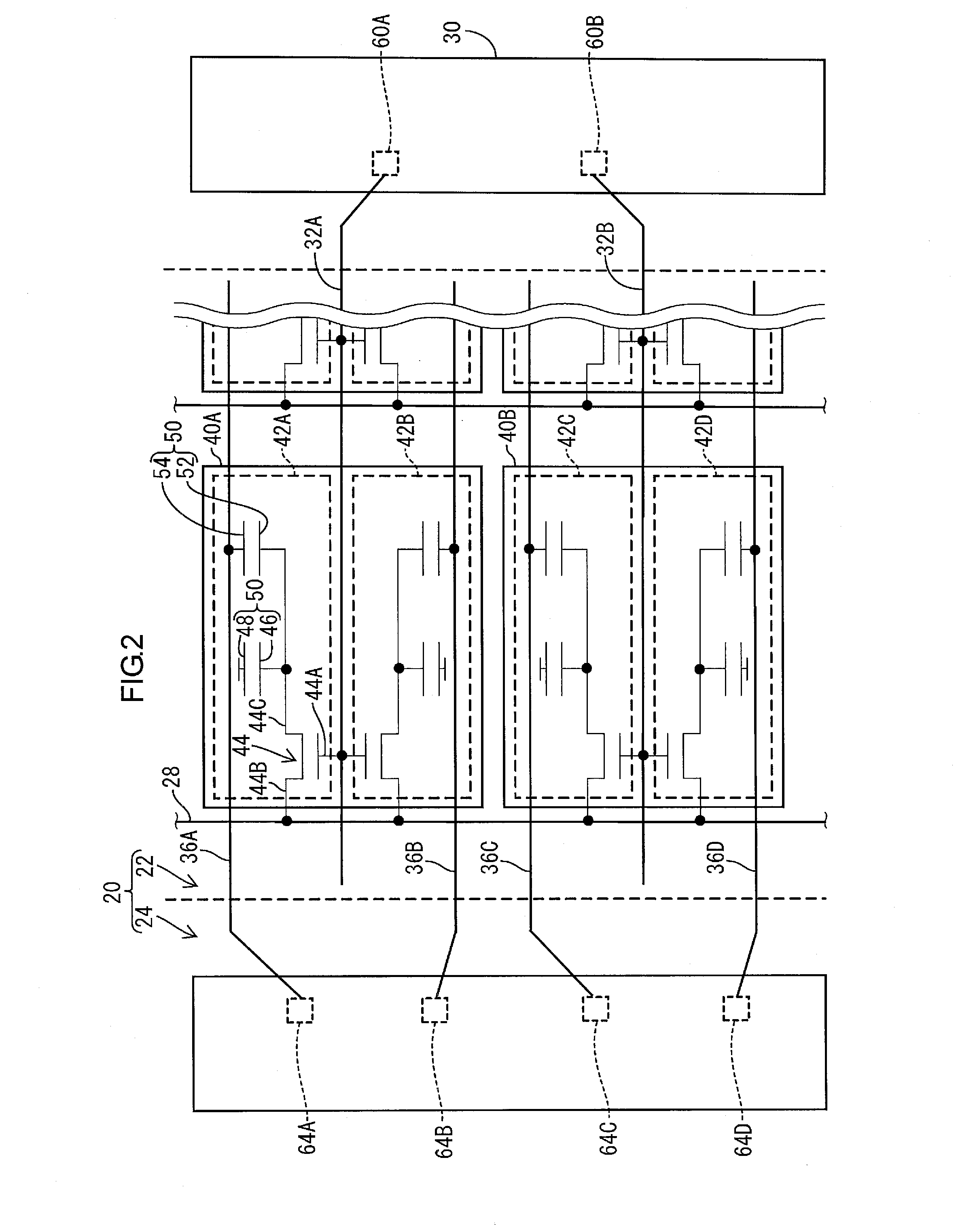
[0048]The liquid crystal panel 20 includes a display section 22 and a frame section 24 around the display section 22. In the display section 22, a plurality of pixels 40 are provided. On an outer su...

second embodiment

[0060]A second embodiment is described with reference to FIG. 4. As illustrated in FIG. 4, in a display device 10 of this embodiment, a trunk line 66 is provided on the frame section 24 of a liquid crystal panel 20. The display device 10 of this embodiment is different from the display device 10 of the first embodiment.

[0061]If each pixel 40 can have a predetermined light transmission rate and a predetermined viewing angle, the auxiliary capacitance signal applied to each of the auxiliary capacitance lines 36 may not be all varied. For example, the same kind of the auxiliary capacitance signal may be applied to a group of a predetermined number of auxiliary capacitance lines 36. This simplifies the configuration of the auxiliary capacitance driver 34 that generates the auxiliary capacitance signal.

[0062]As illustrated in FIG. 4, in this embodiment, the auxiliary capacitance lines 36 to which the same auxiliary capacitance signal is applied are connected via the trunk line 66 (an exa...

third embodiment

[0065]A third embodiment is described with reference to FIG. 5. As illustrated in FIG. 5, in a display device 10 of this embodiment, the gate driver 30 and the auxiliary capacitance driver 34 are arranged on one side in the first direction of the display section 22 of the liquid crystal panel 20. The display device 10 of the third embodiment is different from the display device 10 of the second embodiment.

[0066]1. Effects of the Third Embodiment

[0067](1) In the display device 10 of this embodiment, the gate driver 30 to which the scanning line 32 is connected and the auxiliary capacitance driver 34 to which the auxiliary capacitance line 36 is connected can be arranged in the same frame section 24. Accordingly, the area of the frame section 24 can be reduced.


PUM


Abstract

A display device 10 according to the present invention includes a plurality of pixels 40 each including a plurality of sub pixels 42, a plurality of auxiliary capacitance lines 36 forming an auxiliary capacitance 56 with the sub pixels 42, and an auxiliary capacitance driver 34 configured to supply an auxiliary capacitance drive signal to the auxiliary capacitance lines 36 and to apply a voltage to the auxiliary capacitance. In the display device 10, the auxiliary capacitance driver 34 includes a plurality of connection terminals 64 each connected to each of the auxiliary capacitance lines 36.

Description

TECHNICAL FIELD[0001]The present invention relates to a display device including a plurality of pixels, in particular to a display device including an auxiliary capacitance line that forms an auxiliary capacitance with the pixels.BACKGROUND ART[0002]In recent years, high-performance display devices such as a large screen television have been widely used. In such a display device, unevenness in a displayed image may largely deteriorate an image quality. Thus, correction of the unevenness is required. The unevenness includes brightness unevenness that may be caused by display brightness varied for each pixel and color unevenness that may be caused by chromaticity difference. In addition to such unevenness, problems of unevenness caused by a dependence of gamma characteristics, which is varied according to a gradation level of the display brightness, on a visual perception are increasing.[0003]Patent Documents 1 and 2 disclose a multi pixel drive method as a technology that can reduce ...

Claims


Application Information

Patent Timeline
IPC IPC(8): G09G5/10
CPCG09G3/3659G09G5/10G09G2320/0233
Inventor NAKAMIZO, MASAHIKOSHIMOSHIKIRYOH, FUMIKAZUSUZUKI, TAKAMITSUHASHIMOTO, AKIFUMI
Owner SHARP KK
Why Eureka
Try Eureka