Display device and television device

Active Publication Date: 2016-03-29
SHARP KK
View PDF15 Cites 2 Cited by
  • Summary
  • Abstract
  • Description
  • Claims
  • Application Information

AI Technical Summary

Benefits of technology

[0022]The present invention provides a display device co

Problems solved by technology

Therefore, an area of the frame portion increases by

Method used


Image

  • Display device and television device
  • Display device and television device
  • Display device and television device

Examples


first embodiment

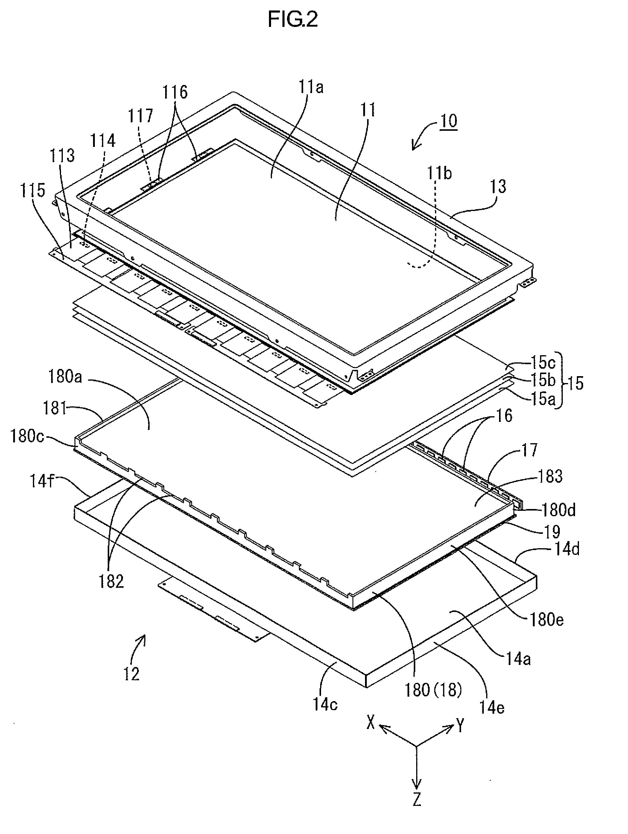
[0035]A first embodiment of the present invention will be described with reference to FIGS. 1 to 4. In this embodiment, a liquid crystal display device 10 and a television device TV will be explained. X-axes, Y-axes, and Z-axes are in some drawings. Directions indicated by the axes in each drawing correspond to directions indicated by the respective axes in other drawings. An upper side in FIGS. 2 and 3 corresponds to a front-surface side and a lower side in FIGS. 2 and 3 corresponds to a rear-surface side.

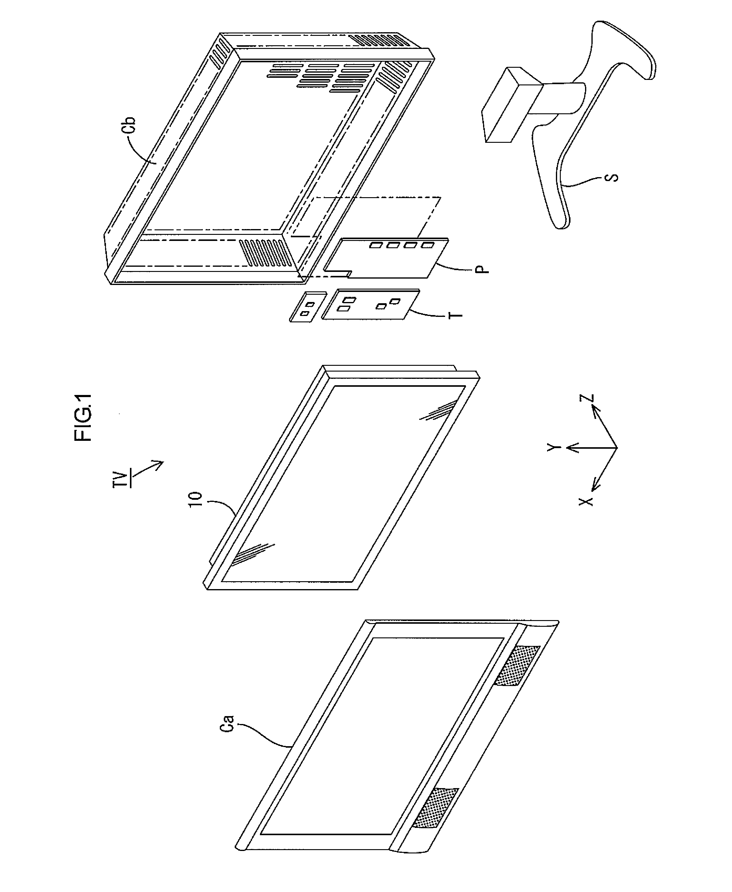
[0036]FIG. 1 is an exploded perspective view illustrating a general configuration of the television device TV according to the first embodiment. As illustrated in FIG. 1, the television device TV of this embodiment includes the liquid crystal display device (a display device) 10, front and rear cabinets Ca, Cb which sandwich and house the liquid crystal display device 10 therebetween, a power supply P, a tuner T, and a stand S. The stand S holds the liquid crystal display device 1...

second embodiment

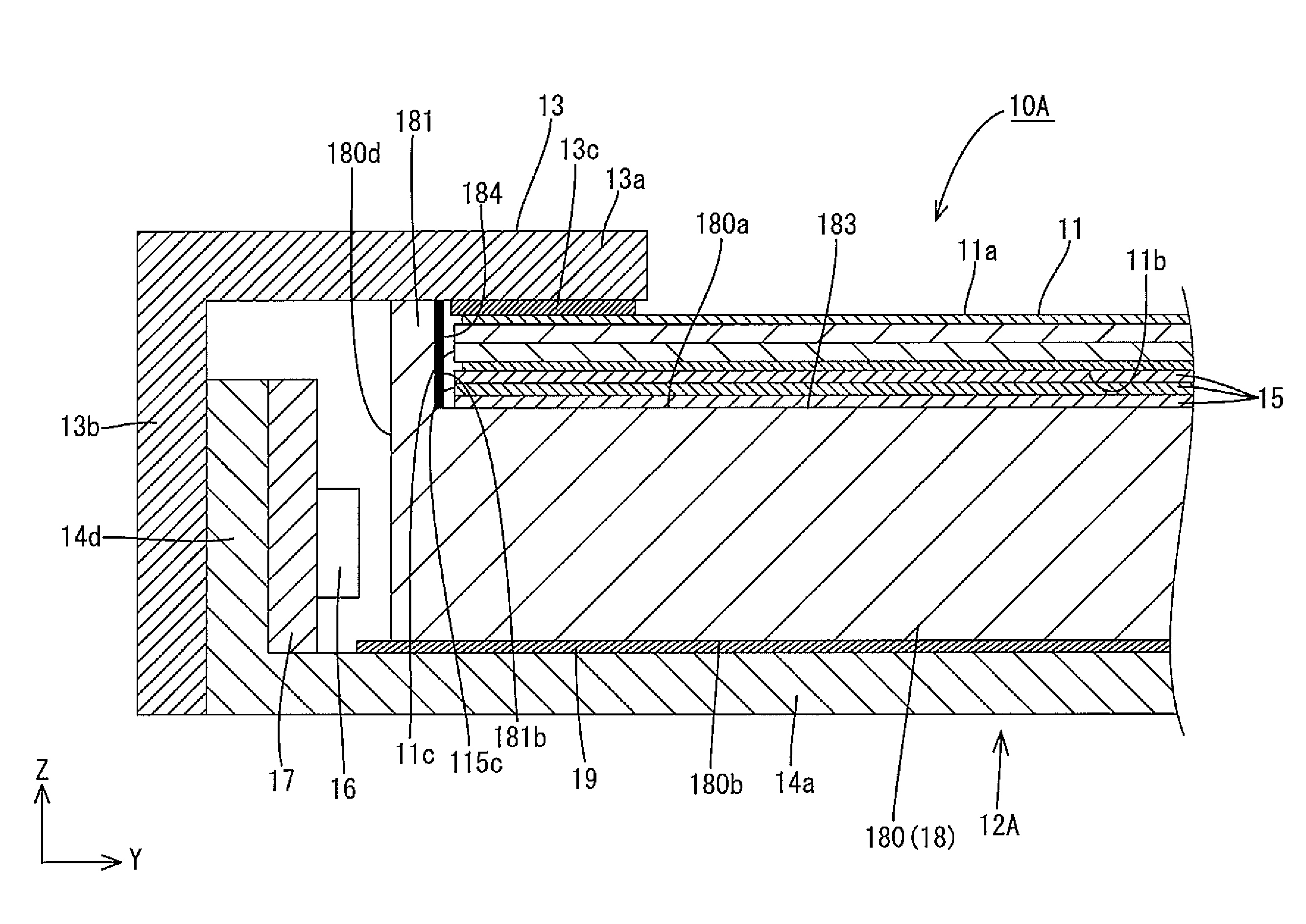
[0068]A second embodiment of this invention will be described with reference to FIG. 5. The same parts as those in the first embodiment will be indicated by the same symbols and will not be explained. FIG. 5 is a magnified cross-sectional view illustrating a liquid crystal display device 10A according to the second embodiment of the present invention. A basic configuration of the liquid crystal display device 10A (a lighting device 12A) according to this embodiment is similar to that of the first embodiment. In the liquid crystal display device 10A according to this embodiment, a light blocking layer 184 is arranged on an inner wall surface 181b of the wall 181 included in the light guide plate 18. The light blocking layer 184 blocks light. The inner wall surface 181b of the wall 181 faces the end portion 11c of the liquid crystal panel 11 arranged in the recess 183. The wall 181 faces the end portion 115c of the optical sheet set 15. The light from the LED light sources 16 enter th...

third embodiment

[0070]A third embodiment of this invention will be described with reference to FIG. 6. FIG. 6 is a magnified cross-sectional view illustrating a liquid crystal display device 10B according to the third embodiment of the present invention. A basic configuration of the liquid crystal display device 10B (a lighting device 12B) according to this embodiment is similar to that of the first embodiment. However, in the liquid crystal display device 10B according to this embodiment, a configuration of a wall 181B included in a light guide plate 18B is different from that of the first embodiment. The wall 181B included in the light guide plate 18B according to this embodiment is formed integrally with a body 180B like the first embodiment. However, the wall 181B is made of a material different from that of the body 180B. The body 180B of the light guide plate 18B is made of the same material as the light guide plate 18 (the body 180) of the first embodiment (the material capable of high light...


PUM


Abstract

A display device 10 according to this invention includes a light source 16, a display panel 11, an optical member 18, and walls 181. The display panel 11 includes a rear surface 11b that light from the light source 16 reaches, and a display surface 11a that displays an image with using the light reaching the rear surface 11b. The optical member 18 has a plate-like shape and includes facing portion 180a that faces the rear surface 11b. The light from the light source 16 transmits through the optical member 18 so as to exit the optical member 18 from the facing portion 180a toward the rear surface 11b. The walls 181 rise respective peripheral edge portions of the facing portion 180a and surround periphery of the display panel 11.

Description

TECHNICAL FIELD[0001]The present invention relates to a display device and a television device.BACKGROUND ART[0002]Liquid crystal panels are used display panels that display images in display devices such as television devices, portable phones, or portable information terminals. External light is required to be used to display images on the liquid crystal panels. Therefore, such display devices include the liquid crystal panels and lighting units (backlight units) as disclosed in Patent Document 1. Such a lighting unit is arranged on a back side of the liquid crystal panel and configured to irradiate planar light toward the back surface of the liquid crystal panel.[0003]In the display device, the liquid crystal panel is fixed by a frame as disclosed in Patent Document 1. The frame is a frame member made of metal or resin and supports a peripheral edge portion of the liquid crystal panel with its inner edge portion from the back surface side of the liquid crystal panel. The liquid cr...

Claims


Application Information

Patent Timeline
IPC IPC(8): G02F1/1333G02F1/1335F21V8/00
CPCG02F1/133308G02B6/0088G02F1/1336G02F1/133504G02F1/133512G02F1/133524G02F2001/133322G02F1/133322
Inventor KUBO, KATSUHIRO
Owner SHARP KK
Why Eureka
Try Eureka