
Display device with attached touch panel

a touch panel and display device technology, applied in the field of touch panel display devices, can solve the problems of ineffective region of display panel that cannot be reduced in size and the inability to reduce the frame area, so as to reduce the ineffective region outside the image display region and reduce the frame area

Inactive Publication Date: 2012-08-16
SHARP KK
View PDF2 Cites 15 Cited by
  • Summary
  • Abstract
  • Description
  • Claims
  • Application Information

AI Technical Summary

Benefits of technology

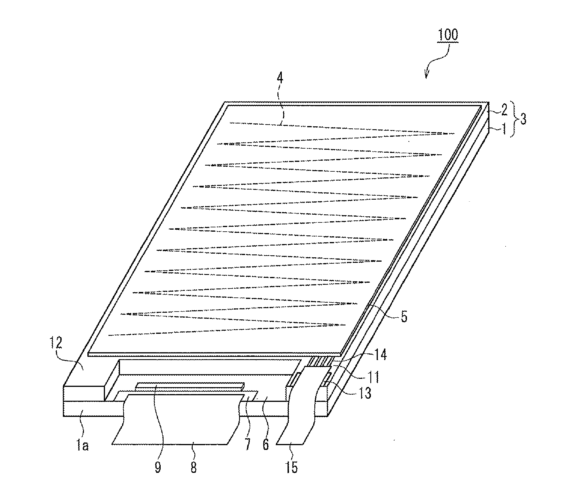
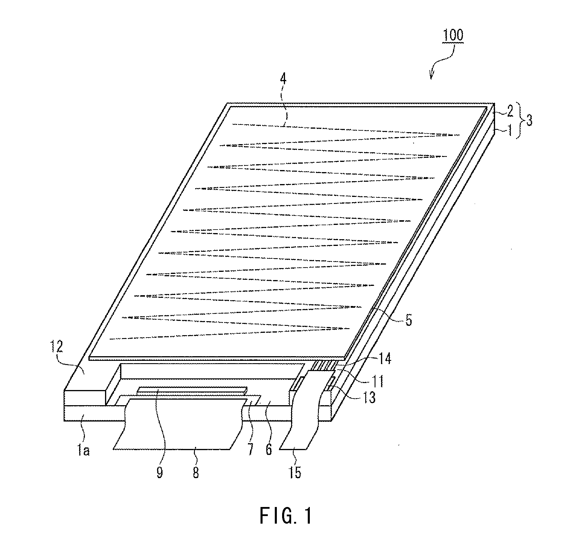
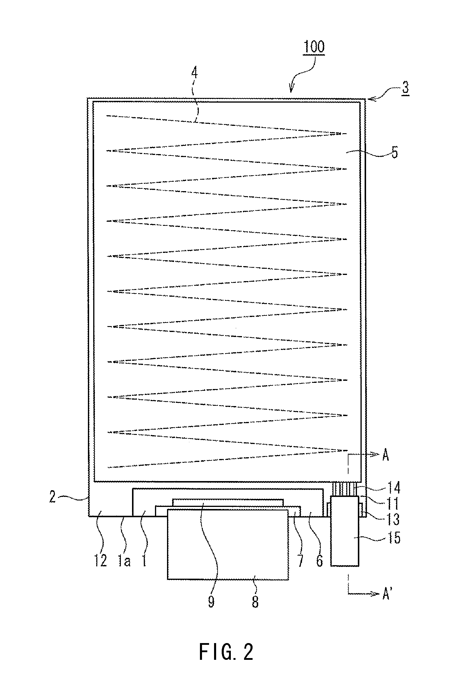
[0013]In view of this, an object of the present invention is to reduce the frame area in a display device with an attached touch panel in which a touch electrode is provided on a front substrate of a display panel, by raising the proportion of the image display region to the overall surface area of the display device.
[0015]According to the present invention, the signal output terminal for outputting a touch position signal obtained from the touch electrode is formed in the peripheral region in which the driving electrode terminal is provided, thus enabling reducing the ineffective region outside the image display region. This enables reducing the frame area.

Problems solved by technology

Particularly in the case of a display device with an attached touch panel, the frame area needs to be reduced in the state where the touch panel and the substantially rectangular display panel are stacked, and therefore even if the above-described overhang portion is provided, the ineffective region of the display panel cannot be reduced in size, and the frame area cannot be reduced.

Method used


Image

  • Display device with attached touch panel
  • Display device with attached touch panel
  • Display device with attached touch panel

Examples


embodiment

[0025]The following describes an embodiment of the present invention with reference to the drawings.

[0026]Note that an example of the configuration of a liquid crystal display device with an attached touch panel used for image display in a PDA or the like is taken as an example of a display device with an attached touch panel in the following description of an embodiment. However, the following description is not intended to limit the configuration or application of the display device with an attached touch panel. The display device with an attached touch panel may be a cold-cathode display device that employs field emission or an organic or inorganic EL display, or a display device including any of various types of display panels such as a plasma display panel (PDP). Also, the display device with an attached touch panel is not limited to being applied to a mobile device such as a PDA, and can be used as any of various types of stationary display devices with an attached touch panel...


PUM


Abstract

In a display device with an attached touch panel in which a touch electrode is provided on a front substrate of a display panel, the frame area is reduced by raising the proportion of the image display region to the overall surface area of the display device. The display device with an attached touch panel (100) (liquid crystal display device with an attached touch panel) includes a display panel (3) (liquid crystal panel) that has a back substrate (1) and a front substrate (2) stacked on the back substrate (1) such that a portion of the back substrate (1) is exposed, a driving electrode terminal (7) for connection with an external circuit being formed on the exposed portion of the back substrate (1), and a touch electrode (4) that is formed on the front substrate (2) of the display panel (3). An extension portion (11) is provided on the front substrate (2) on one side of the driving electrode terminal (7), the extension portion (11) extending toward the side of the back substrate (1) where the driving electrode terminal (7) is formed. A signal output terminal (13) for outputting a touch position signal detected by the touch electrode (4) to the external circuit is provided on the extension portion (11).

Description

TECHNICAL FIELD[0001]The present invention relates to a display device with an attached touch panel configured including a display panel for displaying images and the like and a touch electrode formed on a front substrate of the display panel, so as to be able to detect a touch position.BACKGROUND ART[0002]In recent years, display devices with an attached touch panel have been widely used due to the prevalence of personal digital assistants (PDAs), palmtop computers, mobile gaming devices, and the like. Such display devices with an attached touch panel have a configuration in which a touch panel serving as an input unit is superimposed on a display panel such as a liquid crystal panel, and thus are configured such that input operations can be performed using the touch panel.[0003]For example, with a liquid crystal display device with an attached touch panel, a transparent touch panel is stacked on an image display region of a liquid crystal panel, and images displayed on the liquid ...

Claims


Application Information

Patent Timeline
Patent Type & Authority Applications(United States)
IPC IPC(8): G06F3/041
CPCG06F3/0412
Inventor KITABAYASHI, TADASHI
Owner SHARP KK
Learn More