Optical communication apparatus

Inactive Publication Date: 2013-08-15
MITSUBISHI ELECTRIC CORP
View PDF2 Cites 4 Cited by
  • Summary
  • Abstract
  • Description
  • Claims
  • Application Information

AI Technical Summary

Benefits of technology

The present invention provides a device that can detect and control the dispersion (signal loss) of a transmission line used for optical communication. This is achieved by transmitting a specific pattern of optical signals with a lower bit rate than the data frame, and then receiving the signals from the opposite device. When a frame loss is detected, the device controls the dispersion amount to reduce errors. This invention can improve the quality of optical communication and minimize errors without the need for additional interfaces.

Problems solved by technology

The delay difference (wavelength dispersion) of light due to wavelength will bring about a waveform distortion and degrade a bit error characteristic.
In particular, at a transmission rate not less than 40 Gb / s, since the dispersion tolerance is low and deterioration of transmission performance occurs owing to slight changes in the dispersion amount due to changes in temperature, a high-accuracy dispersion compensation technique is necessary.

Method used


Image

  • Optical communication apparatus
  • Optical communication apparatus
  • Optical communication apparatus

Examples


embodiment 1

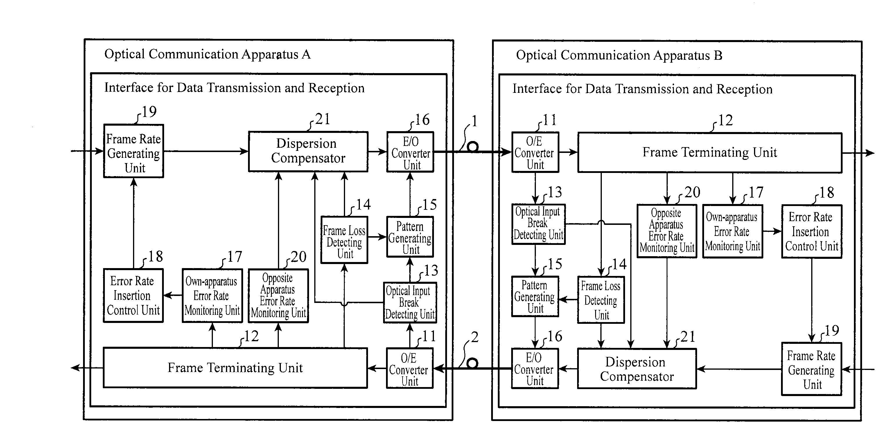
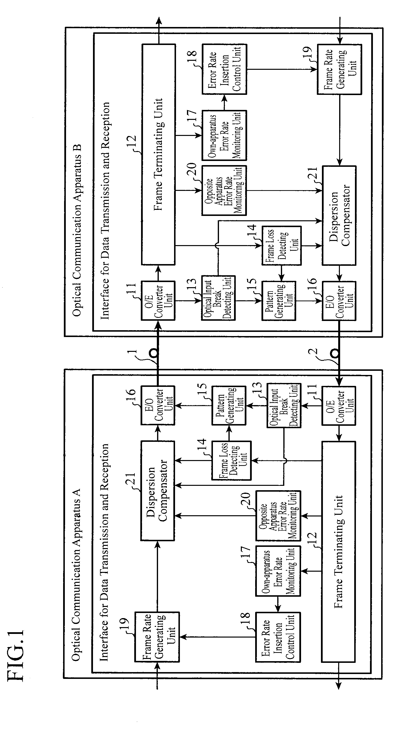
[0027]FIG. 1 is a block diagram showing a configuration of an optical communication apparatus of an embodiment 1 in accordance with the present invention.

[0028]In the example of FIG. 1, an optical communication apparatus A and an optical communication apparatus B with the same configuration are connected via transmission lines (optical fibers) 1 and 2.

[0029]Although the optical communication apparatus A and the optical communication apparatus B incorporate an interface for data transmission and reception, they do not have a dedicated interface for controlling the dispersion amount of the transmission line.

[0030]In FIG. 1, an O / E converter unit 11 receives an optical signal transmitted from the opposite apparatus, and converts the optical signal to an electric signal. Incidentally, the O / E converter unit 11 constitutes an optical signal receiving device.

[0031]A frame terminating unit 12 terminates a data frame (data frame created by a frame generating unit 19 of the opposite apparatu...

embodiment 2

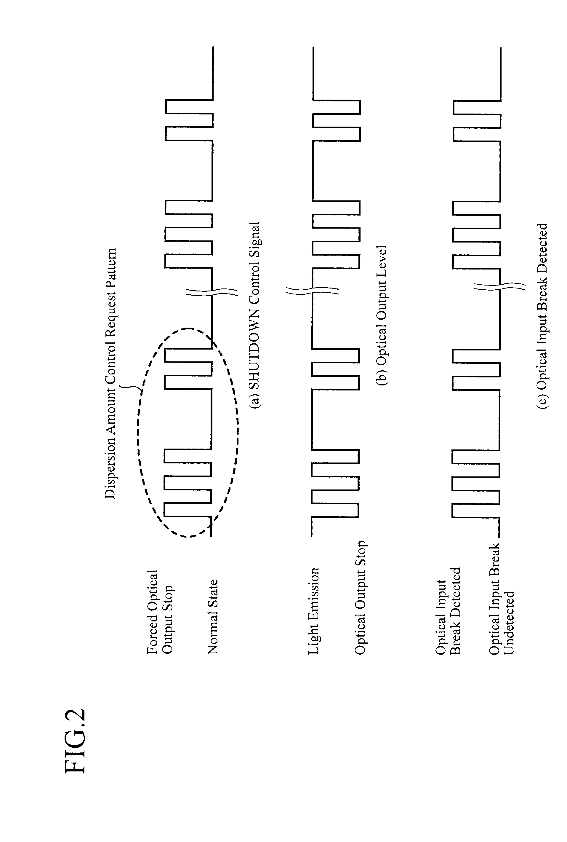
[0101]Although the foregoing embodiment 1 shows an example in which the E / O converter unit 16 carries out the forced optical output stop control (SHUTDOWN control) in accordance with the dispersion amount control request pattern supplied from the pattern generating unit 15 to turn the light on and off, it is also possible to control the signal level of the optical signal to be transmitted in accordance with the dispersion amount control request pattern.

[0102]FIG. 3 is a block diagram showing a configuration of an optical communication apparatus of an embodiment 2 in accordance with the present invention, in which the same reference symbols as those of FIG. 1 designate the same or like portions, and their description will be omitted.

[0103]When the frame loss detecting unit 14 detects the frame loss in the undetected state of the input break of the optical signal by the level monitor 33, the pattern generating unit 31 generates the dispersion amount control request pattern, and contro...

embodiment 3

[0126]FIG. 5 is a block diagram showing a configuration of an optical communication apparatus of an embodiment 3 in accordance with the present invention, in which the same reference symbols as those of FIG. 1 designate the same or like portions, and their description will be omitted.

[0127]When the frame loss detecting unit 14 detects the frame loss in the undetected state of the input break of the optical signal by an optical input break detecting unit 43, a pattern generating unit 41 generates a dispersion amount control request pattern and supplies the dispersion amount control request pattern to the E / O converter unit 16.

[0128]In this case, to transmit the optical signal of the dispersion amount control request pattern at a bit rate lower than the bit rate of transmitting the optical signal of the data frame (transmit at a transmission rate not greater than a quarter of the transmission rate of the data frame, for example), the pattern generating unit 41 generates the dispersion...


PUM


Abstract

An apparatus has frame loss detecting unit 14 for detecting frame loss of a data frame; dispersion amount control request transmission device for transmitting, when the frame loss detecting device 14 detects the frame loss in an undetected state of an input break of an optical signal by optical input break detecting unit 13, an optical signal of a dispersion amount control request pattern to the opposite apparatus at a bit rate lower than that for transmitting the optical signal of the data frame until the frame loss becomes undetected state; and dispersion amount control request receiving device for receiving the optical signal of the dispersion amount control request pattern transmitted from the opposite apparatus, wherein dispersion compensator 21 controls the dispersion amount of transmission line between the apparatus and the opposite apparatus when the dispersion amount control request receiving device receives the optical signal of a specific pattern.

Description

TECHNICAL FIELD[0001]The present invention relates to an optical communication apparatus that seeks to minimize the error rate of the opposite apparatus by controlling the dispersion amount of a transmission line.BACKGROUND ART[0002]Recently, with an increase of a network transmission rate, optical fiber communication systems have been spreading rapidly.[0003]As general characteristics of an optical fiber, propagation velocity of light differs depending on its wavelength, and the propagation velocity of a shorter wavelength is usually faster.[0004]Accordingly, the propagation velocity becomes lower as the wavelength becomes longer so that the receiving time at a receiving apparatus varies owing to slight difference in the wavelength.[0005]The delay difference (wavelength dispersion) of light due to wavelength will bring about a waveform distortion and degrade a bit error characteristic.[0006]As for the effect of the waveform distortion due to wavelength dispersion, although it is sm...

Claims


Application Information

Patent Timeline
IPC IPC(8): H04B10/2507
CPCH04B10/2507H04L1/20H04L1/0001
Inventor SATO, SHOICHI
Owner MITSUBISHI ELECTRIC CORP
Why Eureka
Try Eureka