Apparatus and method for repeating signal by using wireless optical transmission

a wireless optical transmission and repeating signal technology, applied in the field of apparatus and method for repeating signals by using wireless optical transmission, can solve the problems of limited mobile communication service coverage area, limited intensity of transmisible radio waves, and limited repeater gain, so as to minimize the error rate and ensure the stability of data transmission.

Inactive Publication Date: 2007-04-24
PANTECH CO LTD
View PDF5 Cites 3 Cited by
  • Summary
  • Abstract
  • Description
  • Claims
  • Application Information

AI Technical Summary

Benefits of technology

[0027]It is, therefore, an object of the present invention to provide an apparatus and method for repeating signal by using wireless optical transmission for simultaneously transmitting the two identical copies of a wireless optical signal through two different routes, thereby minimizing the error rate and securing a stable environment for data transmission.

Problems solved by technology

On the other hand, the one major drawback of the repeater 21 is that a radio wave signal between transmitting and receiving antennas could be coupled together and it causes oscillations.
For keeping the RF signals separate, antennas need to be installed with a vertical clearance and the gain of the repeater must be limited.
Therefore, the intensity of transmissible radio waves becomes limited and the mobile communication service coverage area would be limited too.
On the other hand, the potential pitfall of using the cable optical repeater 22 and an optical cable is that this optical transmission technology can not be embraced prior to the provision of relevant infrastructure.
In addition to the above, installing, hiring and fixing an optical cable are extremely costly in most cases.
On the other hand, the one major drawback of using the microwave repeater 23 is that the use of frequencies within microwave bandwidth brings up the legal and security issues such as paying fees for the usage, dealing with local authority and wire-tapping.
Referring to FIG. 2D, the miniature base station 24 is a miniaturized version of the base station 11, but otherwise the installation of such station 24 is problematic as well as costly.
It is often the case that the wireless optical signal transmission is climate-dependent and vulnerable to a malfunction caused by an external force.
Here, if data is to be transmitted through an optical cable at the rate of 1 Gbps, that is, 1 bit is roughly equivalent to 1 ns, an instant blockage in the optical cable will do a significant damage to the transmission of data as a whole, resulting in data being corrupted.
This is the one major drawback of the wireless optical signal transmission.

Method used


Image

  • Apparatus and method for repeating signal by using wireless optical transmission
  • Apparatus and method for repeating signal by using wireless optical transmission
  • Apparatus and method for repeating signal by using wireless optical transmission

Examples


Embodiment Construction

[0037]Other objects and aspects of the invention will become apparent from the following description of the embodiments with reference to the accompanying drawings, which is set forth hereinafter.

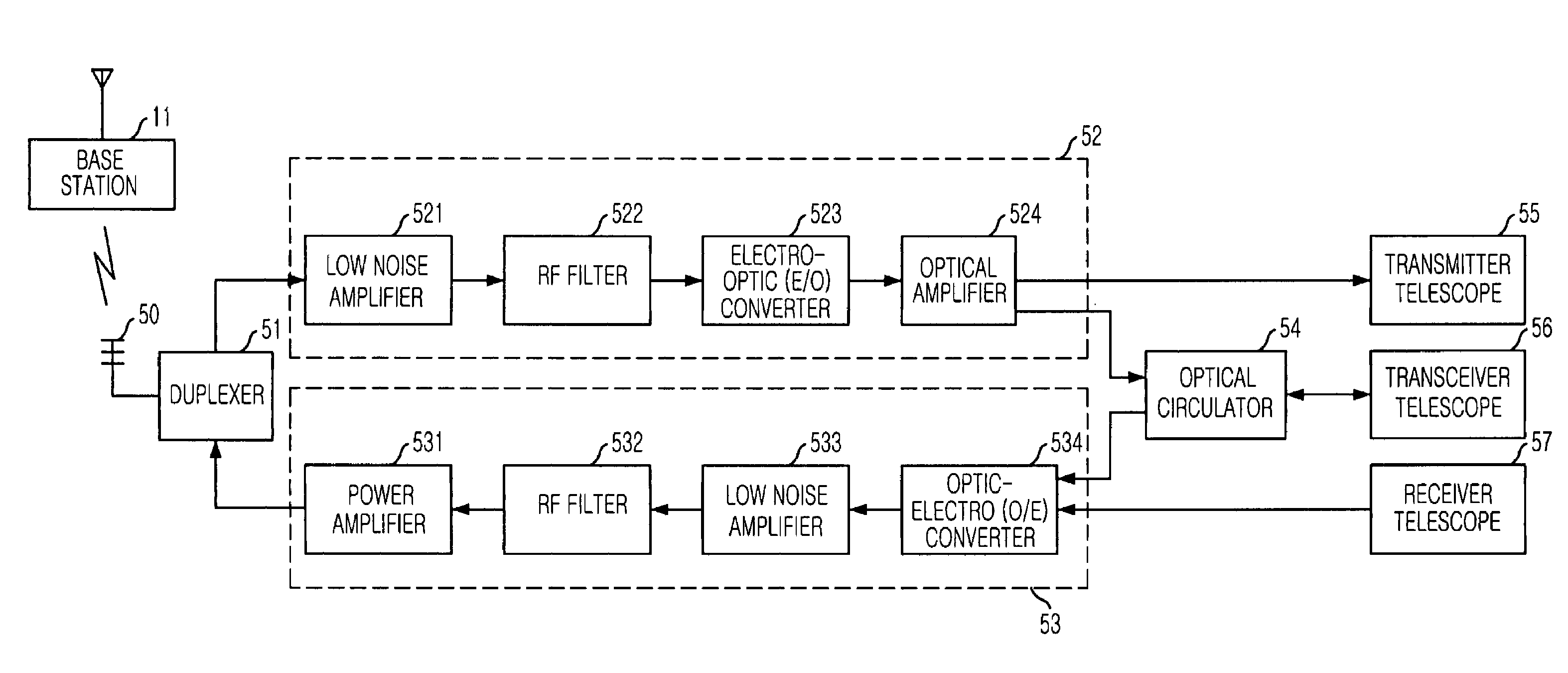
[0038]FIG. 5 is a perspective view illustrating the configuration of a donor device used in a repeater using wireless optical transmission in accordance with a preferred embodiment of the present invention.

[0039]Referring to FIG. 5, the donor device includes a donor antenna 50, a duplexer 51, a forward process unit 52, a transmitter telescope 55, an optical circulator 54, a transceiver telescope 56, a receiver telescope 57 and a backward process unit 53.

[0040]The donor antenna 50 transmits a RF signal to the base station 11, and vice versa. The duplexer 51 passes the RF signal transmitted from the base station 11 to a forward process unit 52 via the donor antenna 50. On the contrary, the duplexer 51 passes a RF signal transmitted from a backward process unit 53 on to the base station 11 via...


PUM


Abstract

A repeating apparatus and method using wireless optical transmission is disclosed. The repeating apparatus includes a donor device for transmitting two identical copies of an optical signal by receiving a RF signal from a base station and electro-optic converting the RF signal to an optical signal, and for transmitting a RF signal by receiving two identical copies of the optical signal and optic-electro converting the optical signal to a RF signal; and a coverage device for transmitting a RF signal to a mobile communication terminal by receiving two identical copies of the optical signal from the donor device and optic-electro converting the two identical copies of the optical signal to the RF signal, and transmitting two optical signals to the donor device by receiving the RF signal from the mobile communication terminal and elector-optic converting the RF signal to the optical signal.

Description

FIELD OF THE INVENTION[0001]The present invention relates to an apparatus and method for repeating signal by using wireless optical transmission; and, more particularly, to an apparatus and method for repeating signal by using wireless optical transmission for simultaneously transmitting the two identical copies of a wireless optical signal through two different routes, thereby minimizing the error rate and securing a stable environment for data transmission.DESCRIPTION OF RELATED ART[0002]Hereinafter, a mobile communication system will be quoted as a working example of the preferred embodiments of the present invention.[0003]FIG. 1 is a perspective view of a wireless communication system.[0004]Referring to FIG. 1, the mobile communication system includes a mobile communication terminal 10, a base station 11, a base station controller 12, a switching center 13, a location register 15 and a gateway switching center 14.[0005]The base station 11 provides a wireless connection between t...

Claims


Application Information

Patent Timeline
Patent Type & Authority Patents(United States)
IPC IPC(8): H04B10/00H04B10/10
CPCH04B10/1123H04B10/2575H04B10/29H04B7/14
Inventor LEE, JONG-SEOB
Owner PANTECH CO LTD
Why Eureka
Try Eureka