Antenna system for satellite communication and method for tracking satellite signal using the same

a satellite communication and satellite technology, applied in the direction of antennas, antenna details, antenna adaptation in movable bodies, etc., can solve the problems of increasing manufacturing costs, complex control, and increasing tracking speed and position control, so as to reduce tracking loss and increase tracking accuracy.

Inactive Publication Date: 2005-05-05
INTELLECTUAL DISCOVERY CO LTD
View PDF12 Cites 35 Cited by
  • Summary
  • Abstract
  • Description
  • Claims
  • Application Information

AI Technical Summary

Benefits of technology

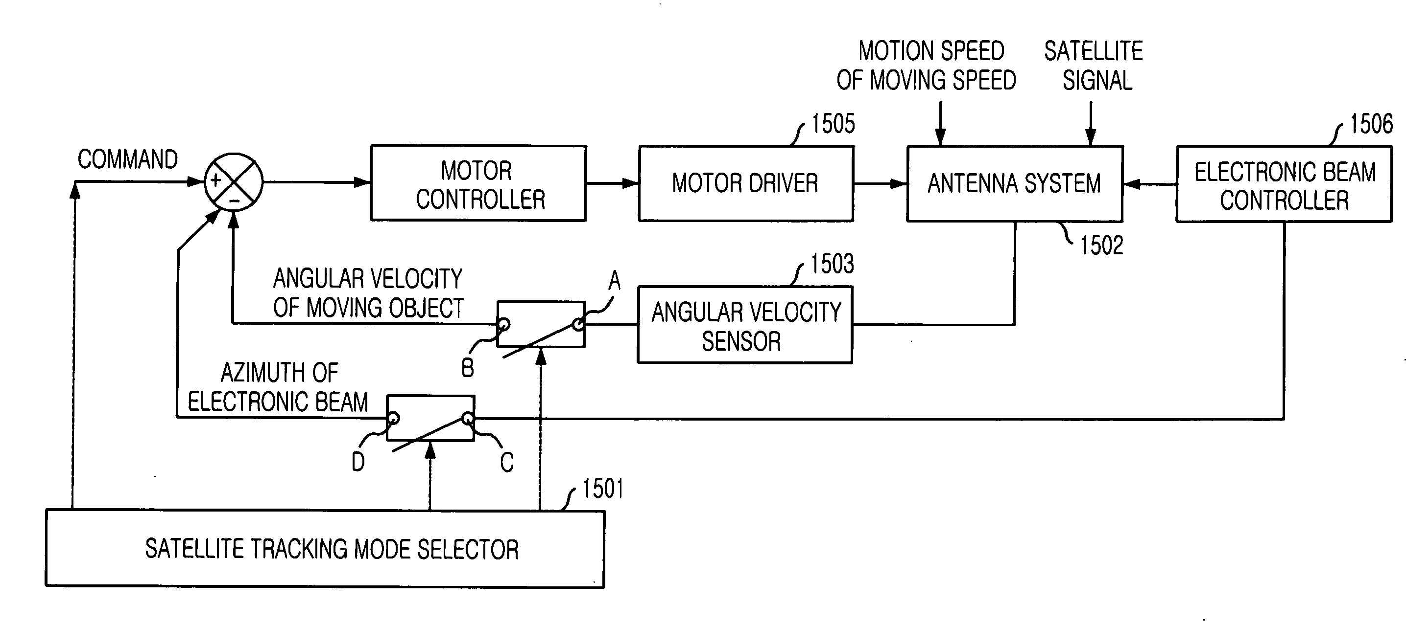
[0025] It is, therefore, an object of the present invention to provide an antenna system for satellite communication and a method for tracking a satellite signal using the antenna system, which is capable of increasing a tracking accuracy and reducing a tracking loss, in which both one-dimensional phase array control of the elevation is mixed with one-dimensional mechanical control of azimuth and a double beam satellite tracking method and an electronic direction detecting method are used.
[0040] Meanwhile, some of the reception signals are used as the satellite tracking signal. Based on the reception signals, the transmission frequency and the position of the satellite are calculated automatically and the phase of the transmission active channel module is controlled, thereby providing a stable communication environment.

Problems solved by technology

However, the conventional method has a problem in that the tracking speed and position control is complex.
Further, in the case of a method for controlling a phase of the unit antenna element on 2-dimension by using the phased array antenna, there occurs a problem in that a control is complex due to a large number of elements to be phase-controlled and a manufacturing cost increases.

Method used


Image

  • Antenna system for satellite communication and method for tracking satellite signal using the same
  • Antenna system for satellite communication and method for tracking satellite signal using the same
  • Antenna system for satellite communication and method for tracking satellite signal using the same

Examples


Embodiment Construction

[0066] Hereinafter, a detailed description of the preferred embodiments will be made with reference the accompanying drawings.

[0067]FIG. 6 is an explanatory diagram of a satellite communication system in accordance with the present invention.

[0068] As shown, a satellite 610 and a vehicle 620 or a vessel 630 transmit / receive up / down satellite signals through antenna systems 621 and 631 for the satellite communication in accordance with the present invention, thereby maintaining a communication environment between each other.

[0069] In a transmission, that is, when the vehicle 620 transmits a signal to the satellite 610, the antenna system 621 for the satellite communication of the moving vehicle 620 receives a signal from a communication terminal 622 disposed inside the vehicle and then converts the signal into a satellite frequency signal to output a radio frequency signal to the satellite 610. In a reception, that is, when the vehicle 620 receives a signal from the satellite 610,...


PUM


Abstract

Provided is an antenna system for satellite communication and a method for tracking satellite signals using the same, in which moving vehicles or vessels can perform a satellite multimedia communication. The method for tracking a satellite signal using the antenna system includes the steps of: a) setting a satellite signal reception environment by performing an electronic tracking in the elevation direction through an electronic beam steering control and performing a mechanical tracking for driving a rotating element in an azimuth direction; and b) stopping a drive of the rotating element in the azimuth direction, and setting a satellite signal transmission environment by using the satellite signal reception environment. According to the present invention, since both one-dimensional phase array control of the elevation and azimuth and one-dimensional mechanical control are used, it is possible to provide the economical and effective system compared with two-dimensional phase array antenna. Further, the satellite tracking speed performance is improved compared with the two-dimensional mechanically controlled antenna.

Description

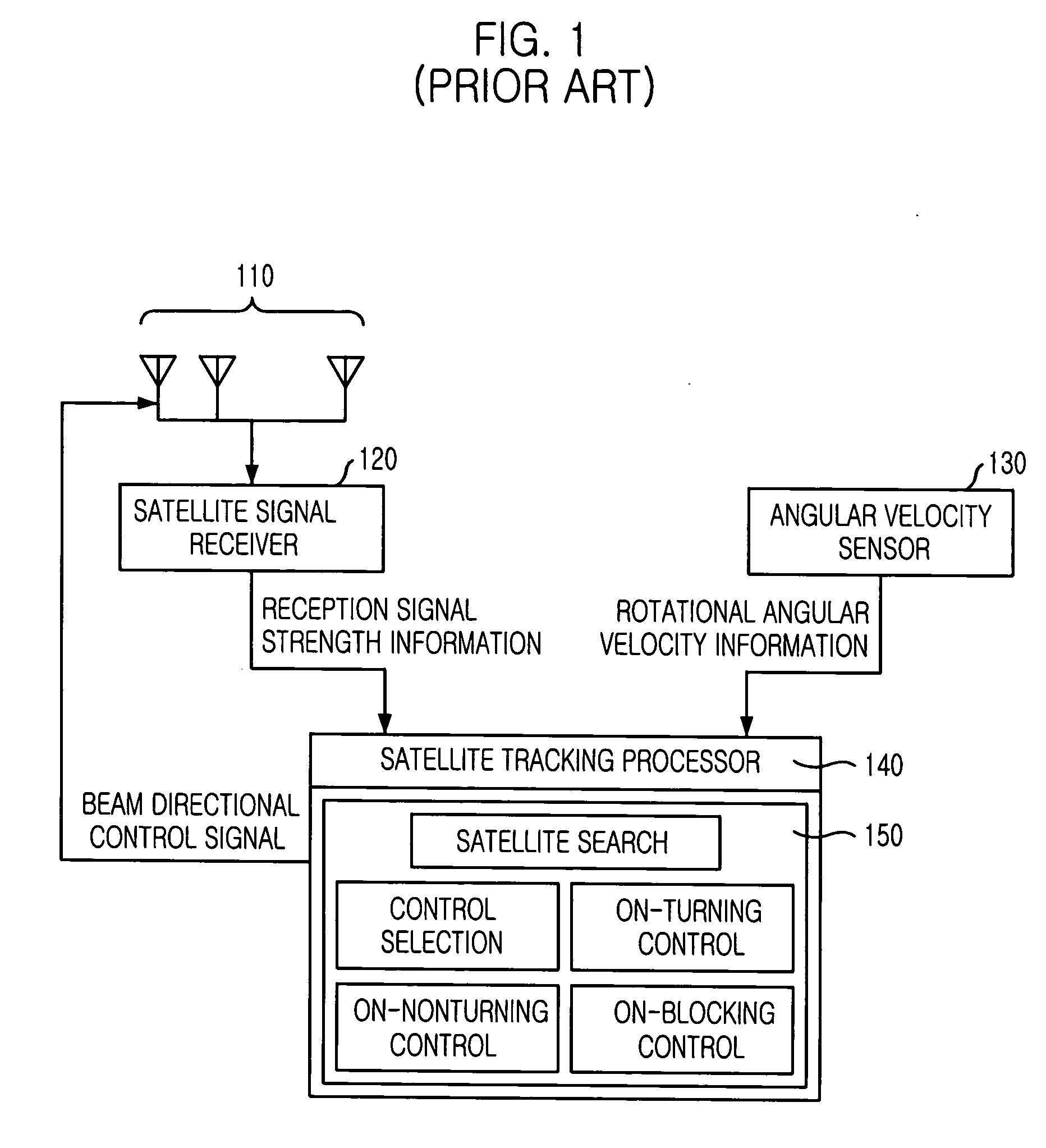
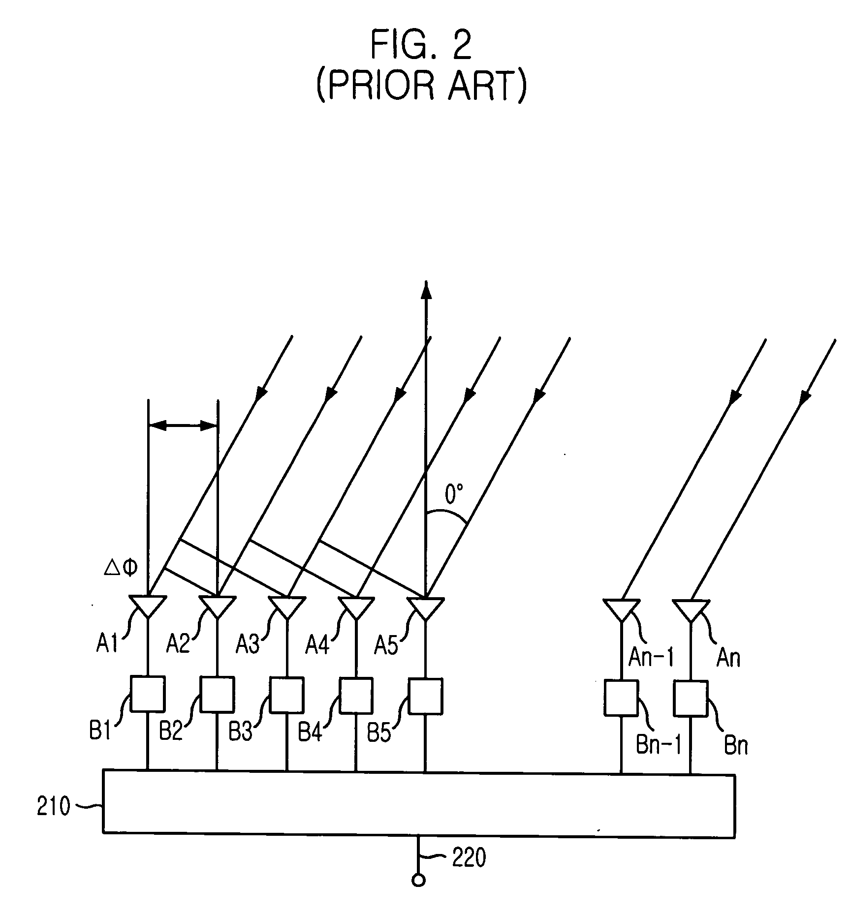
FIELD OF THE INVENTION [0001] The present invention relates to an antenna system for satellite communication and a method for tracking satellite signals using the same; and, more particularly, to an antenna system for satellite communication and a method for tracking satellite signals using the same, in which moving vehicles or vessels can perform a satellite multimedia communication. DESCRIPTION OF THE PRIOR ART [0002] A conventional bi-directional satellite communication has widely used a low-capacitance voice signal communication using a low earth orbit-satellite (LEO-satellite) based on a concept of mobile phone, and a satellite multimedia communication using a fixed antenna system based on a concept of very small aperture terminal (VSAT). [0003] In the bi-directional communication using a satellite, a mobile communication terminal system requires an antenna having a satellite tracking function in order to maintain a stable communication environment. [0004]FIG. 1 shows a basic c...

Claims


Application Information

Patent Timeline
Patent Type & Authority Applications(United States)
IPC IPC(8): H01Q3/04H01Q1/32H01Q3/08H01Q3/26H01Q3/34H01Q21/08H04B7/155
CPCH01Q1/3275H01Q3/26H01Q3/08H01Q21/08
Inventor PARK, UNG-HEEJEON, SOON-IKSON, SEONG-HOYUN, JAE-SEUNG
Owner INTELLECTUAL DISCOVERY CO LTD
Why Eureka
Try Eureka