Multi-beam cellular communication system

Active Publication Date: 2010-11-02
BLACKBERRY LTD
View PDF14 Cites 36 Cited by
  • Summary
  • Abstract
  • Description
  • Claims
  • Application Information

AI Technical Summary

Benefits of technology

[0022]Due to the reliance on the spatial separation of the beams to discriminate between the beams, it is desirable to operate an inter beam handoff scheme to reduce the loss of data traffic when an end user equipment enters a region of high carrier/interference levels, such as a cusp region between adjacent beams. In this case when it is determined, for example by a processor of the base station, that an end user equipment is located in such a region, in response to such a determination data traffic may be sent to that end user equipment on the same codes simultaneously on multiple beams, for example by a base station scheduling device.
[0023]In addition because spatial separation is relied upon to discriminate between beams it is useful to apply adaptive modulation and coding (AMC) to the data traffic transmitted over the beams. AMC can be effectively exploited according by the present invention because traffic is sent on all of the beams in a sector simultaneously and so a stable interference environment is provided. In one embodiment the carrier/interference level on the common pilot channel is measured and in response to the measured level appropriate modulation and coding is applied to the signals transmitted on the beams. In an alternative embodiment, which has the advantage of not r

Problems solved by technology

In general it is desired to have as few base stations as possible, as they are expensive, require extensive

Method used


Image

  • Multi-beam cellular communication system
  • Multi-beam cellular communication system
  • Multi-beam cellular communication system

Examples


Embodiment Construction

[0052]There will now be described by way of example the best mode contemplated by the inventor for carrying out the invention. In the following description, numerous specific details are set out in order to provide a complete understanding of the present invention. It will be apparent, however, to those skilled in the art that the present invention may be put into practice with variations of the specific.

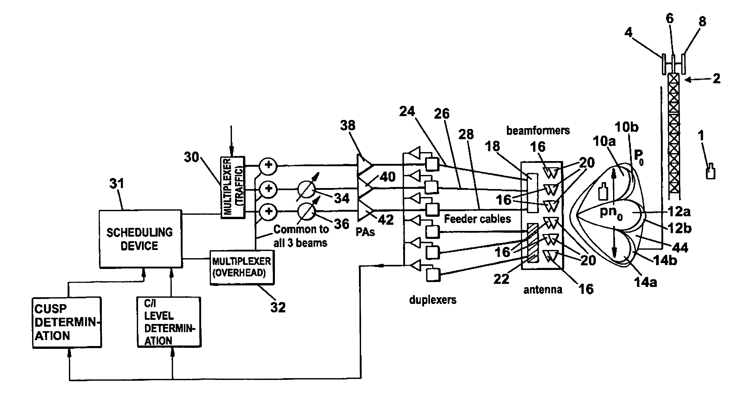
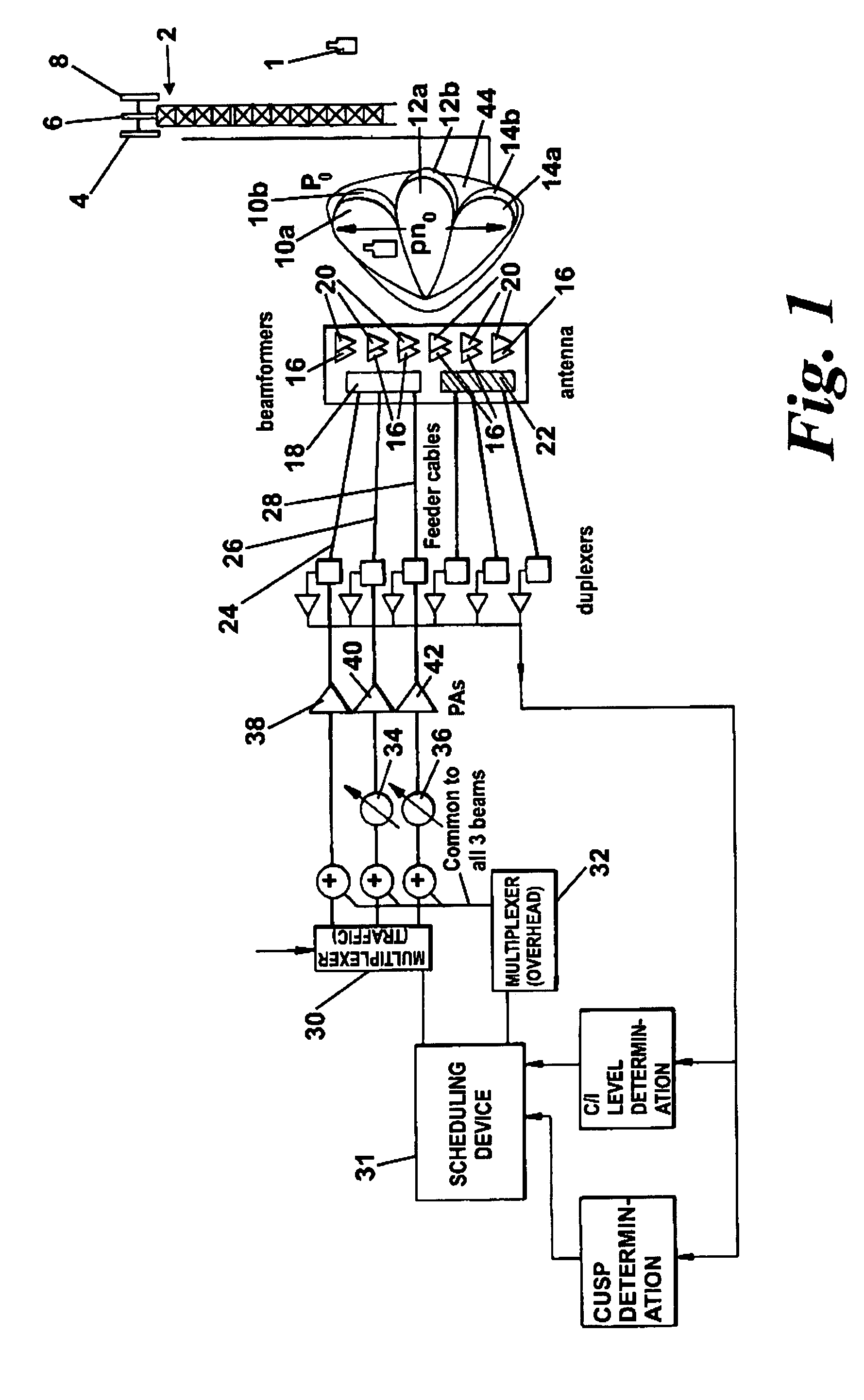
[0053]FIG. 1 shows an antenna arrangement for providing coverage in one sector of a three sector cell of a cellular communication system, which cell is serviced by a base station (2). The base station (2) is equipped with three such antenna arrangements (4, 6, 8) off-set in azimuth angle by 120°, so that each antenna arrangement covers a sector of the cell. The antenna arrangement defines a first narrow transmit / receive beam (10a) and diversity receive beam (10b), a second narrow transmit / receive beam (12a) and diversity receive beam (12b), a third narrow transmit / receive beam (14a)...


PUM


Abstract

A cellular communication system comprising a plurality of geographically spaced base stations (2) each of which comprises an antenna arrangement (4, 6, 8) per base station sector, each of which antenna arrangements has an antenna element for generating an array of narrow beams (10, 12, 14) covering the sector. Timeslots are simultaneously transmitted over each of the beams so as to generate successive sets of simultaneously transmitted timeslots per sector. The timeslots are each split into multiple orthogonal codes, for example Walsh codes. The communication system additionally comprising a scheduling device (31) for allocating for successive sets of timeslots common overhead channels, including a common pilot channel, which are allocated to the same sub-set of codes of each timeslot in the set. For successive sets of timeslots different data traffic is allocated to the same sub-set of codes of each timeslot in the set. This effectively generates a sector wide antenna beam carrying the common overhead channels and a plurality of narrow beams each of which carry different data traffic. Inter-beam interference is addressed by the application of Adaptive Modulation and Coding and by an inter-beam handoff scheme. The handoff scheme ensures that when an end user equipment is located in a cusp region between adjacent beams the antenna arrangement simultaneously transmits data traffic to that mobile station on at least both of the adjacent beams.

Description

FIELD OF THE INVENTION[0001]This invention relates to multi-beam cellular communication systems and in particular to methods and apparatus for increasing the capacity of such systems.BACKGROUND OF THE INVENTION[0002]Digital cellular systems, such as Code Division Multiple Access (CDMA) and Universal Mobile Telephony System (UMTS) systems, are currently used for providing telecommunications to stationary and mobile end user equipments. The mobile end user equipments may be mobile stations, for example mobile telephones and mobile computing devices. Such digital cellular systems divide a geographical area to be covered by the communication system into a plurality of cell areas. Within each cell is positioned a base station with which a plurality of end user equipments located within the cell communicate.[0003]In general it is desired to have as few base stations as possible, as they are expensive, require extensive effort in obtaining planning permission and in some areas suitable bas...

Claims


Application Information

Patent Timeline
IPC IPC(8): H04B7/212H01Q1/24H01Q3/26H01Q21/20H01Q25/00H04B7/04H04W16/24H04W16/28
CPCH01Q1/246H01Q3/2617H01Q21/205H01Q25/002H04B7/0408H04W72/0446H04W16/28H04W24/08H04W52/42H04B7/0491H04W16/24H04B7/2628H04L5/0007H04J13/0044H04J13/0048H04L1/0003H04L1/0009H04L5/005
Inventor WILSON, FIONAGALE, SIMON
Owner BLACKBERRY LTD
Why Eureka
Try Eureka