

Liquid delivery tank with expansion chamber
a technology of liquid delivery tank and expansion chamber, which is applied in the field of beverage forming system, can solve the problems of inability to deliver heated liquid from the tank, inability to deliver water from the brew chamber outlet, and inability to achieve precise volume of water
- Summary
- Abstract
- Description
- Claims
- Application Information
AI Technical Summary
Benefits of technology
Problems solved by technology
Method used
Image

Examples
Embodiment Construction
[0027]It should be understood that aspects of the invention are described herein with reference to certain illustrative embodiment and the figures. The illustrative embodiments described herein are not necessarily intended to show all aspects of the invention, but rather are used to describe a few illustrative embodiments. Thus, aspects of the invention are not intended to be construed narrowly in view of the illustrative embodiments. In addition, it should be understood that aspects of the invention may be used alone or in any suitable combination with other aspects of the invention.
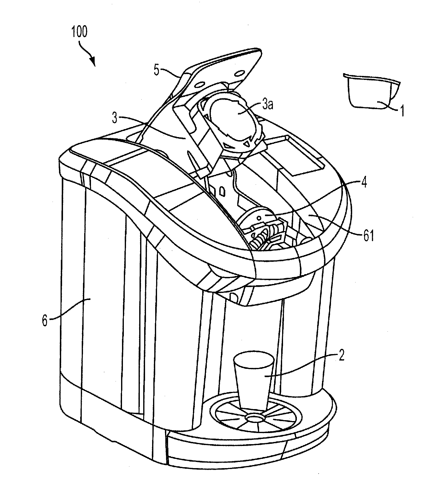
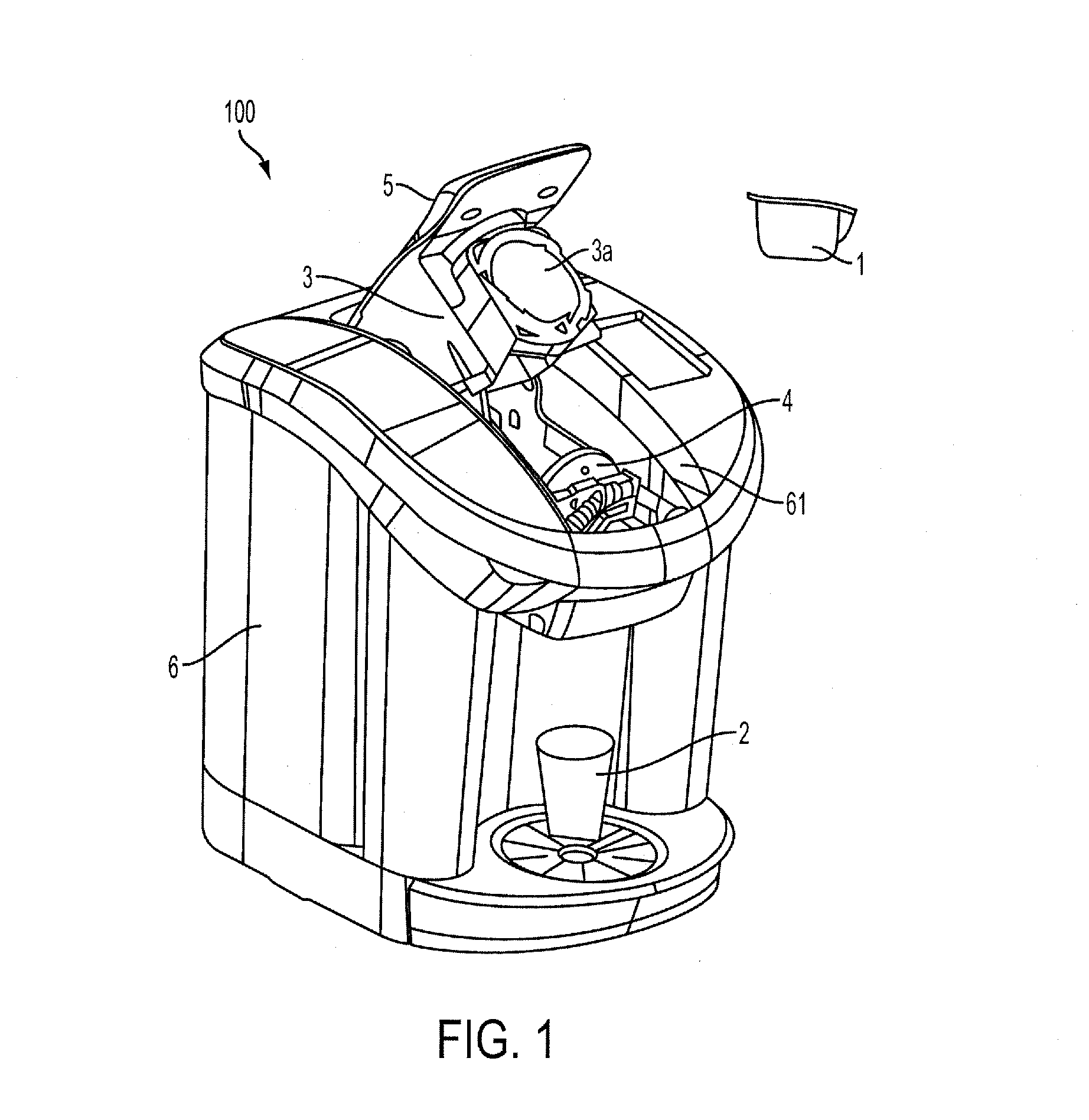
[0028]FIG. 1 shows a perspective view of a beverage forming system 100. Although the beverage forming system 100 may be used to form any suitable beverage, such as tea, coffee, other infusion-type beverages, beverages formed from a liquid or powdered concentrate, soups, juices or other beverages made from dried materials, or other, in this illustrative embodiment, the system 100 is arranged to form coff...
PUM
 Abstract
Description
Claims
Application Information