Body cavity drainage devices and related methods

a technology of body cavity and drainage device, which is applied in the direction of multi-lumen catheter, other medical devices, catheters, etc., can solve the problems of prolonging the hospital stay

Active Publication Date: 2013-08-15
LAZARUS MEDICAL TECH LLC
View PDF12 Cites 25 Cited by
  • Summary
  • Abstract
  • Description
  • Claims
  • Application Information

AI Technical Summary

Problems solved by technology

The need for multiple incisions may generally result in an extended hospital stay from a patient suffering from a severe case of pleurisy.

Method used


Image

  • Body cavity drainage devices and related methods
  • Body cavity drainage devices and related methods
  • Body cavity drainage devices and related methods

Examples


Embodiment Construction

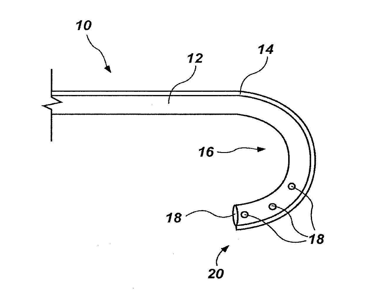
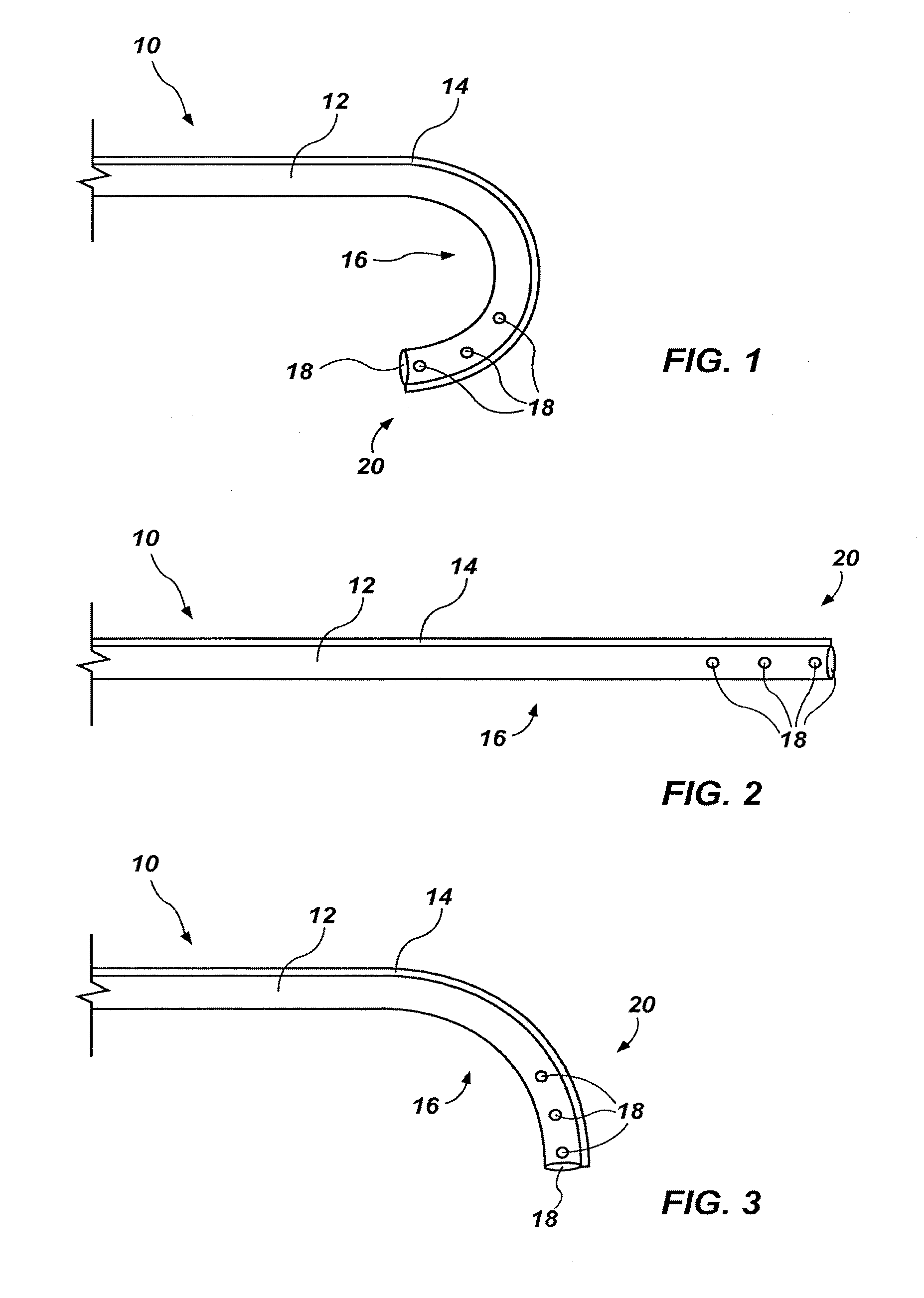
[0052]In some embodiments, a drainage device may include a drainage tube configured to change shape in response to fluid pressure to facilitate the movement of a distal end thereof

[0053]In one embodiment, as shown in FIG. 1, a drainage tube 10 may be generally configured as a catheter and may include a plurality of lumens. For example, the drainage tube 10 may include an open lumen 12 and a closed lumen 14. The drainage tube may further include a biasing structure 16, such as an elastic material region (e.g., flexible material region).

[0054]The open lumen 12 may include at least one opening 18 proximate to a first distal end 20 thereof and, in some embodiments, may include a plurality of openings 18 proximate to the first distal end 20. The one or more openings 18 may be defined by a one or more of apertures, porous regions, and other fluid permeable structures. The open lumen 12 may additionally include an opening at an opposing, second distal end that may be selectively coupled to...


PUM


Abstract

Body cavity drainage devices and associated methods are disclosed herein. In some embodiments a body cavity drainage device comprises a drainage tube having a proximal end and a distal end; and an automated means to move the distal end of the drainage tube about a body cavity of a patient. In some embodiments, the distal end of the drainage tube may be moved by one or more of the application of a magnetic field, the insertion or withdrawal of fluid from a closed lumen, and manipulation by an external motion generator. In additional embodiments, a body cavity drainage device includes at least a second open lumen for the insertion of a fluid into a body cavity. In yet further embodiments, an internal tissue may be massaged from within a body cavity of a patient.

Description

CROSS-REFERENCE TO RELATED APPLICATIONS[0001]This application is a continuation-in-part of U.S. patent application Ser. No. 13 / 045,274, which claims the benefit of U.S. Provisional Application Ser. No. 61 / 312,878, filed Mar. 11, 2010, entitled “BODY CAVITY DRAINAGE DEVICE AND RELATED METHODS,” the disclosure of each of which is hereby incorporated herein by this reference in its entirety.BACKGROUND[0002]1. Field[0003]Embodiments of the invention relate to body cavity drainage devices and related methods.[0004]2. State of the Art[0005]Drainage devices, especially for the evacuation of a pleural cavity, may consist of a hollow flexible tube inserted through an incision into the pleural cavity. The shape and configuration of the pleural cavity often necessitates multiple incisions to be made to permit the drainage tube to reach various locations in the pleural cavity. The need for multiple incisions may generally result in an extended hospital stay from a patient suffering from a sever...

Claims


Application Information

Patent Timeline
Patent Type & Authority Applications(United States)
IPC IPC(8): A61M27/00
CPCA61M1/008A61M2025/015A61M27/00A61M25/003A61M25/0041A61M25/0054A61M25/007A61M25/0127A61M25/0136A61M25/0147A61M25/0155A61M2025/0037A61M2025/004A61M2025/0063A61M2210/101A61M1/84A61M1/87
Inventor LAZARUS, HARRISON M.
Owner LAZARUS MEDICAL TECH LLC
Why Eureka
Try Eureka