Tubular apparatus for drainage of the colon and method and guidewire for colonic intubation

a technology of tubular apparatus and colon, which is applied in the field of colon drainage tubular apparatus, can solve the problems of ineffective evacuation of bacteria and gasses generated in the colon, drawbacks of each of these mechanisms and procedures, and inability to effectively evacuate bacteria and gasses, etc., and achieve the effect of preventing damage to the colon walls and easy feeling

Inactive Publication Date: 2005-10-13
LEIBOFF ARNOLD R
View PDF7 Cites 34 Cited by
  • Summary
  • Abstract
  • Description
  • Claims
  • Application Information

AI Technical Summary

Benefits of technology

[0015] It is a still another object of the present invention to provide new techniques and systems for draining and decompressing the colon which are capable of effectively aspirating the colon and diverting fecal matter away from a colonic anastomosis.
[0025] As such, an exemplifying method for decompressing a colon comprises the steps of inserting a drainage tube having apertures therein through the anus into the colon to extend through substantially the entire colon, fixing the drainage tube in place and applying suction from one end of the drainage tube to cause fecal matter to pass through the apertures into the drainage tube and be withdrawn from the colon. Fixing of the drainage tube in place is necessary to prevent the drainage tube from being discharged from the colon by the natural peristaltic movements of the colon or by inadvertent withdrawal.
[0028] To enhance the performance of such drainage tubes, it is helpful to permit air to enter the tube at the point farthest from the suction supply, behind the column of effluent within the tube. This prevents the establishment of negative pressure behind the column of effluent which would impede drainage. To this end, when a drainage tube is formed so that suction is applied through the forward end of the drainage tube, a channel in a rearward extension portion of the drainage tube can be directly open to or in communication with the ambient atmosphere and the rearward extension portion can have a smaller cross-section than the main part of the drainage tube. The channel in the rearward extension portion extends out of the patient through the patient's anus to the ambient atmosphere. Otherwise, the main part of the drainage tube can be formed with two lumens, namely, an effluent passage and an air passage alongside the effluent passage and opening to the effluent passage at the rearward end of the drainage tube, but within the colon. The air passage communicates with the ambient atmosphere through an air channel in a forward extension portion of the drainage tube while the effluent passage is coupled to a suction device through a suction channel in the forward extension portion. In this manner, it becomes possible to apply suction continuously through the drainage tube.
[0030] Otherwise, the main part of the drainage tube can be formed with two lumens, namely, an effluent passage and an air passage alongside the effluent passage and opening to the effluent passage at the forward end of the drainage tube, within the colon. The air passage communicates with the ambient atmosphere through an air channel in a rearward extension portion of the drainage tube while the effluent passage is coupled to a suction device through a suction channel in the rearward extension portion. In this manner, it becomes possible to apply suction continuously through the drainage tube
[0032] Threading the filament through the colon wall and into engagement with the guidewire may involve forming the guidewire with a through channel and passing a needle on which the filament is threaded though the channel of the guidewire. Preferably, the channel is formed in a bulbous enlargement of the guidewire to thereby provide the bulbous enlargement with flat sides. As such, the bulbous enlargement can be grasped through the bowel wall to fix the location of the flat sides so that it becomes possible to fix the location of the channel. As such, the needle with attached filament then can be easily passed through the bowel wall and channel.
[0035] The guidewire used in the foregoing method to engage with the filament includes an elongate, resilient shaft and a bulbous enlargement arranged at a distal end of the shaft. The bulbous enlargement has a smooth, arcuate outer surface to prevent damage to the walls of the colon during movement of the guidewire through the colon and includes an engagement structure which enables engagement of the filament thereto. Specifically, the engagement structure may take the form of a channel extending through the bulbous enlargement. This provides the bulbous enlargement with opposed flat sides which can be easily felt to thereby enable the location of the channel to be determined by the surgeon by touch alone. The channel may have an axis perpendicular to an axis of the shaft.

Problems solved by technology

There are drawbacks to each of these mechanisms and procedures.
However, gastric aspiration is often incomplete and succuss entericus produced by the bowel, and bacteria and gasses generated within the bowel, are not effectively evacuated.
In spite of these deficiencies, nasogastric tubes are still used by many surgeons after colonic surgery, but are decreasingly popular.
While nasointestinal tubes (e.g., a Cantor Tube) may decompress the small bowel slightly better, they may not effectively prevent gastric ileus.
They are usually placed preoperatively, adding to patient discomfort, and they are no more effective postoperatively than nasogastric tubes.
Cecostomy tubes and cecostomies are known to be inefficient for diversion of the fecal stream, and have been largely abandoned in favor or ileostomies or colostomies.
Cecostomy tubes and cecostomies are used for colonic decompression but not for fecal diversion and have limited use postoperatively.
Their formation is time consuming and they are fraught with complications such as abscess, hernia, prolapse and stricture.
These stomas may cause intestinal obstruction.
Even after temporary stomas have been closed, the adhesions which have been formed by the creation and closure of the stomas may lead to intestinal obstruction.
Rectal tubes have been used to decompress the rectum, but they typically fail to divert the fecal stream away from an anastomosis and become ineffective when plugged by fecal matter.

Method used


Image

  • Tubular apparatus for drainage of the colon and method and guidewire for colonic intubation
  • Tubular apparatus for drainage of the colon and method and guidewire for colonic intubation
  • Tubular apparatus for drainage of the colon and method and guidewire for colonic intubation

Examples


second embodiment

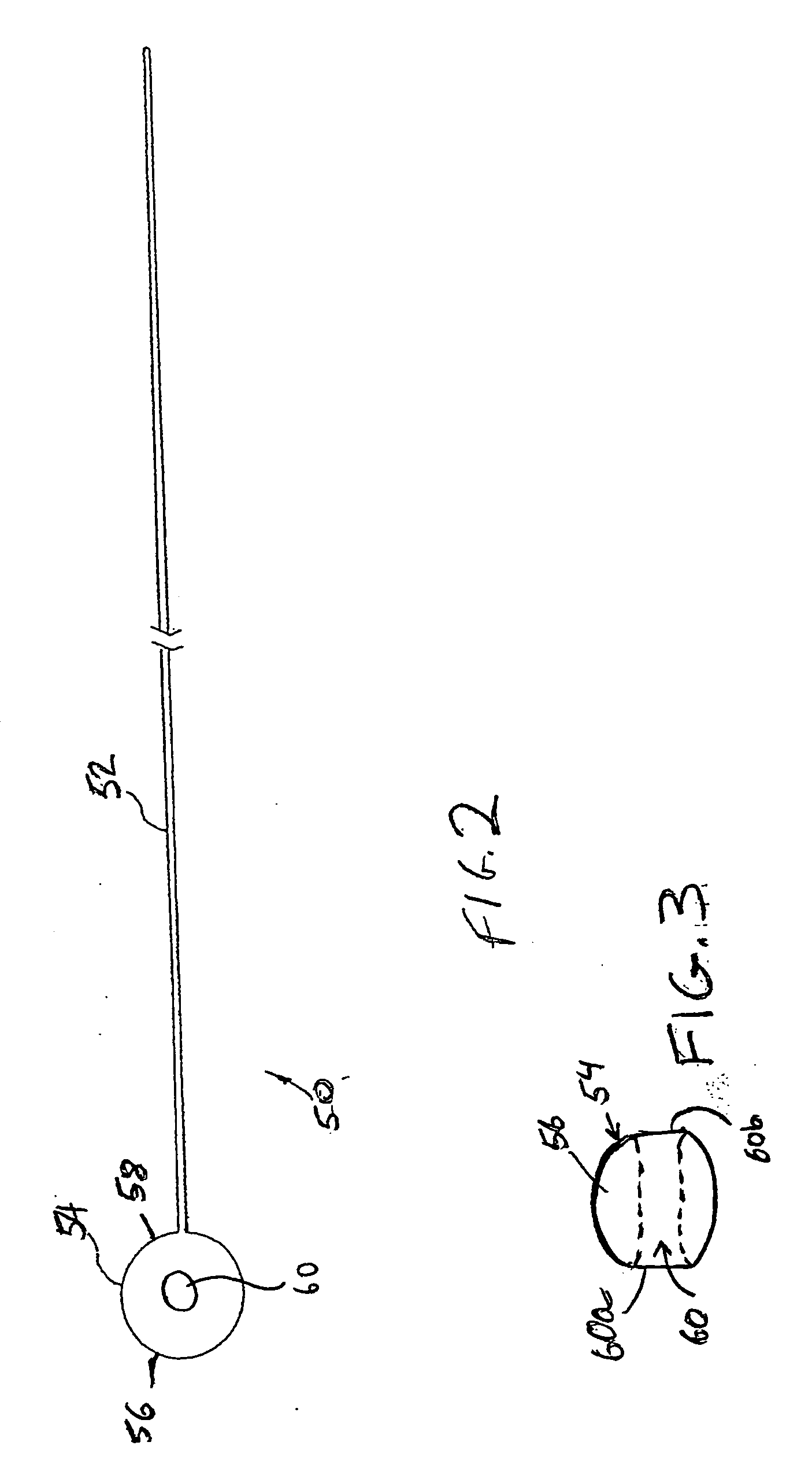
[0065]FIG. 4 shows a guidewire, designated 50a, having a shaft 52a having a substantially circular cross-section and which is tapered so that its diameter in proximity to the bulbous enlargement 54 is smaller than its diameter farther from the bulbous enlargement 54. This gives the guidewire 50a more flexibility near the bulbous enlargement 54, facilitating manipulation of the bulbous enlargement 54 and advancement through the bowel. Instead of a circular cross-section, the shaft 52a may have other cross-sectional shapes.

third embodiment

[0066]FIG. 5 shows a guidewire 50b having a shaft 52b which is constructed of a straight or tapering central metal core wire 62 surrounded by a wire coil 64. This configuration increases the diameter of the shaft 52b while maintaining the flexibility of the shaft 52b. The larger diameter of the shaft 52b allows for easier and safer handling of the guidewire 50b and makes it less likely to damage the wall of the bowel.

[0067] It is also conceivable to make the shaft 52 of the guidewire 50 of constant diameter throughout, but with the portion thereof attached to the bulbous enlargement 54 more flexible than the remainder of the shaft 52. For example, the flexibility of a segment of metal or plastic can be increased without altering its diameter. Another option is to form the shaft from a tapering metal core surrounded by a constant diameter coil.

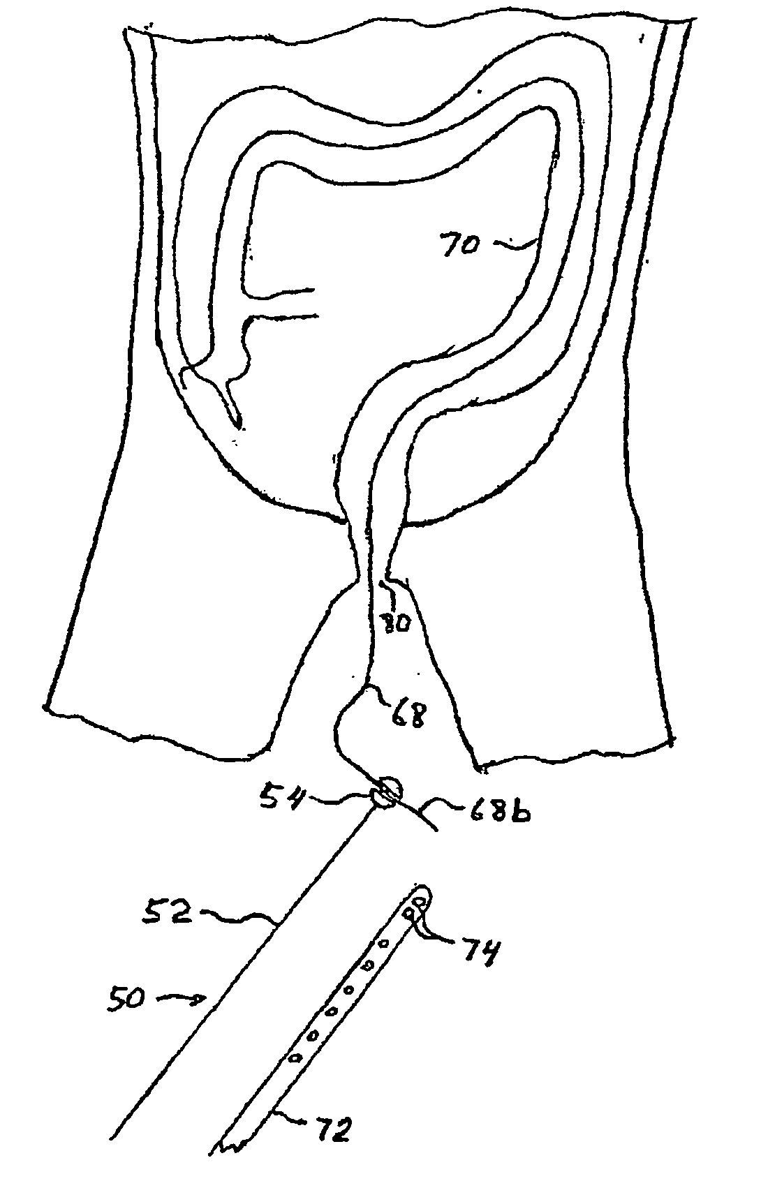
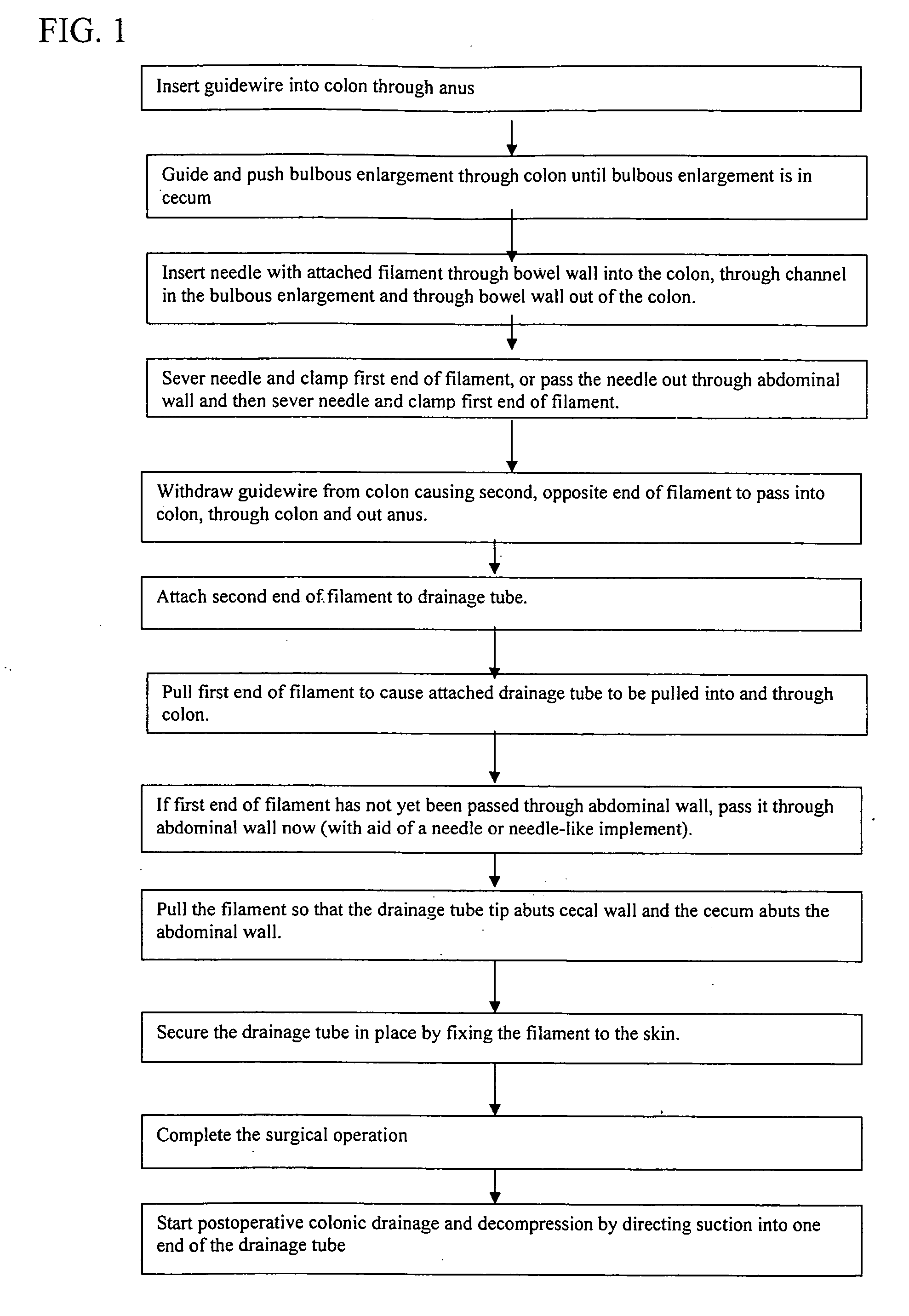
[0068] Referring back to FIG. 1, after the guidewire 50 is situated in the colon with the bulbous enlargement 54 at the most proximal portion...

first embodiment

[0098] A first embodiment applying this alternative is shown diagrammatically in FIG. 15 wherein the drainage tube 72C has a main part 73 having a substantially uniform cross-section and a forward extension portion 90 of the drainage tube 72C passes through the cecal wall 76 and the abdominal wall 48. The forward extension portion 90 includes a channel communicating with the interior lumen in the main part 73. Apertures 74 are formed only in that portion of the drainage tube 72C that will be situated in the colon 70, i.e., the main part 73, and not in the forward extension portion 90 situated between the cecal wall 76 and the suction device 78.

[0099] The forward extension portion 90 of the drainage tube 72C can be coupled to a suction device 78. A rearward extension portion 75 of the drainage tube 72C includes a channel communicating with the interior lumen in the main part 73 and which is then left open to the ambient atmosphere. As such, the suction device 78 creates an air flow p...


PUM


Abstract

Method for draining and decompressing a colon in which a drainage tube is inserted through the anus into the colon to extend through the entire colon. The drainage tube is fixed in position and suction is applied therethrough to cause fecal matter to pass therein through apertures and be withdrawn from the colon. The drainage tube is inserted by inserting a guidewire into the colon through the anus, manipulating and pushing the guidewire to the cecum, passing a filament through the colon wall to engage the guidewire, pulling the guidewire out of the colon and anus to draw the filament through the colon and out of the anus, attaching the drainage tube to the filament and drawing the filament with attached drainage tube through the anus into the colon. The invention also relates to constructions of the guidewire, the drainage tube and methods for inserting drainage tubes using guidewires.

Description

FIELD OF THE INVENTION [0001] The present invention relates generally to apparatus and methods for drainage of the colon and more particularly to tubular apparatus insertable into the colon for draining the colon and methods for draining the colon using such a tubular apparatus. [0002] The present invention also relates generally to methods for inserting a tube into a colon and more specifically to methods for inserting drainage tubes into the colon which extend through the entire colon and enable the removal of enteric contents from the entire colon. [0003] The present invention also relates generally to apparatus for aiding insertion of drainage tubes into the colon and more particularly, to guidewires for aiding insertion of drainage tubes into the colon. [0004] The present invention also relates to methods and systems for achieving and maintaining colonic drainage and decompression in the postoperative period. For example, the invention would be used to aspirate the colon follow...

Claims


Application Information

Patent Timeline
Patent Type & Authority Applications(United States)
IPC IPC(8): A61M1/00
CPCA61M2210/1064A61M1/008A61M1/84
Inventor LEIBOFF, ARNOLD R.
Owner LEIBOFF ARNOLD R
Why Eureka
Try Eureka