Fluid measurement sensor attachment structure

a technology of fluid measurement and sensor, which is applied in the direction of liquid/fluent solid measurement, volume metering, instruments, etc., can solve the problems the inability to solve the problem and achieve accurate measurement, increase the sensitivity of the sensor, and avoid the effect of lowering the fluid transport capacity

Active Publication Date: 2013-08-22
NIPPON PILLAR PACKING CO LTD
View PDF32 Cites 12 Cited by
  • Summary
  • Abstract
  • Description
  • Claims
  • Application Information

AI Technical Summary

Benefits of technology

[0007]It is an object of the present invention to provide a fluid measurement sensor attachment structure with which measurements of a fluid flowing through a pipe can be accurately performed without lowering a fluid transport capacity.
[0017]The present invention provides a fluid measurement sensor attachment structure in which a sleeve accommodating a fluid measurement sensor is inserted into a branch pipe among three or more branch pipes branched from a pipe, wherein a protective wall of the sleeve is positioned near a base end of the branch pipes. Accordingly, the sensitivity of the sensor increases, and the flow rate, the fluid pressure, and the like can be accurately measured. Furthermore, since a seal lip is disposed on a circumferential wall near the protective wall, a fluid does not flow into the branch pipe in which the sensor is disposed, and, thus, neither a fluid accumulation nor a pressure loss occurs. Accordingly, the fluid transport capacity is not lowered.
[0018]Furthermore, when a cap member that can be fitted to or screwed onto the branch pipe is used, and a spacer is interposed between the cap member and the sensor, the sleeve can be prevented from being detached, and, moreover, the sensor can be prevented from being shaken because the spacer can press the sensor at appropriate pressure, and, thus, the measurement precision increases.

Problems solved by technology

Furthermore, since a turbulent flow occurs at the branching portion, a fluid accumulation or a pressure loss may occur, which may lower the fluid transport capacity.
It seems that the measured values become closer to accurate ones by projecting the sensor 3 to a point near the flow path P. However, the problem that the transport capacity is lowered cannot be solved by merely arranging the sensor close to the flow path because a turbulent flow occurs due to a fluid flowing into a point between the sensor 3 and a branch pipe 2a.

Method used


Image

  • Fluid measurement sensor attachment structure
  • Fluid measurement sensor attachment structure
  • Fluid measurement sensor attachment structure

Examples


Embodiment Construction

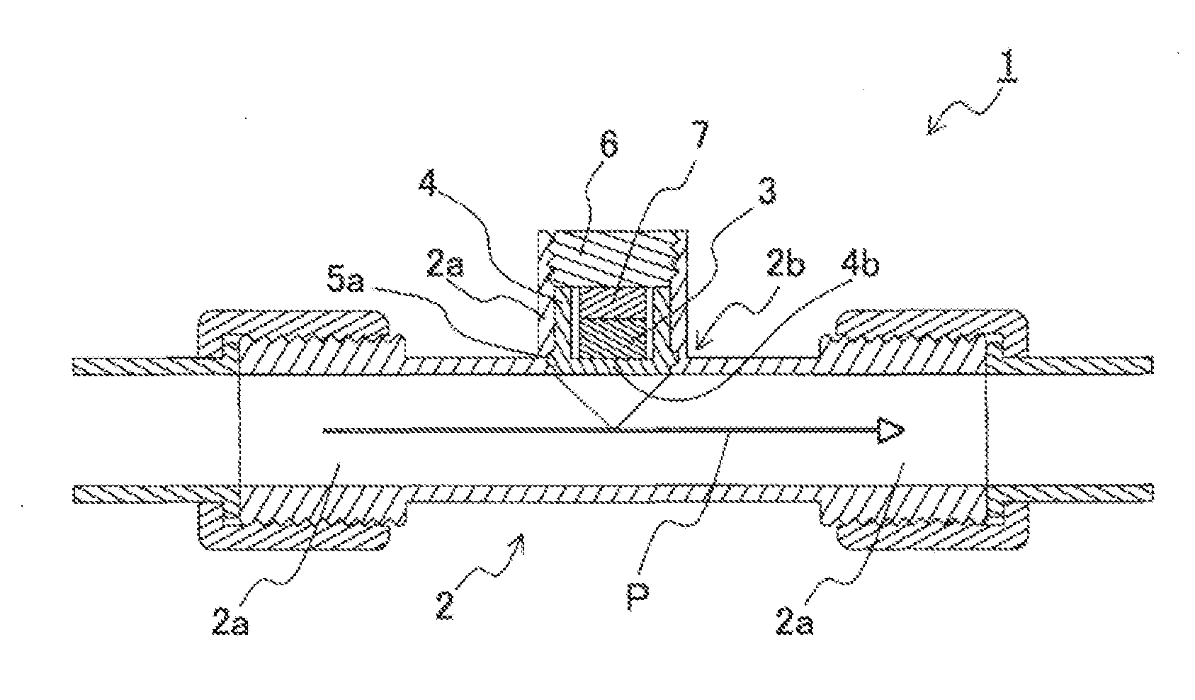
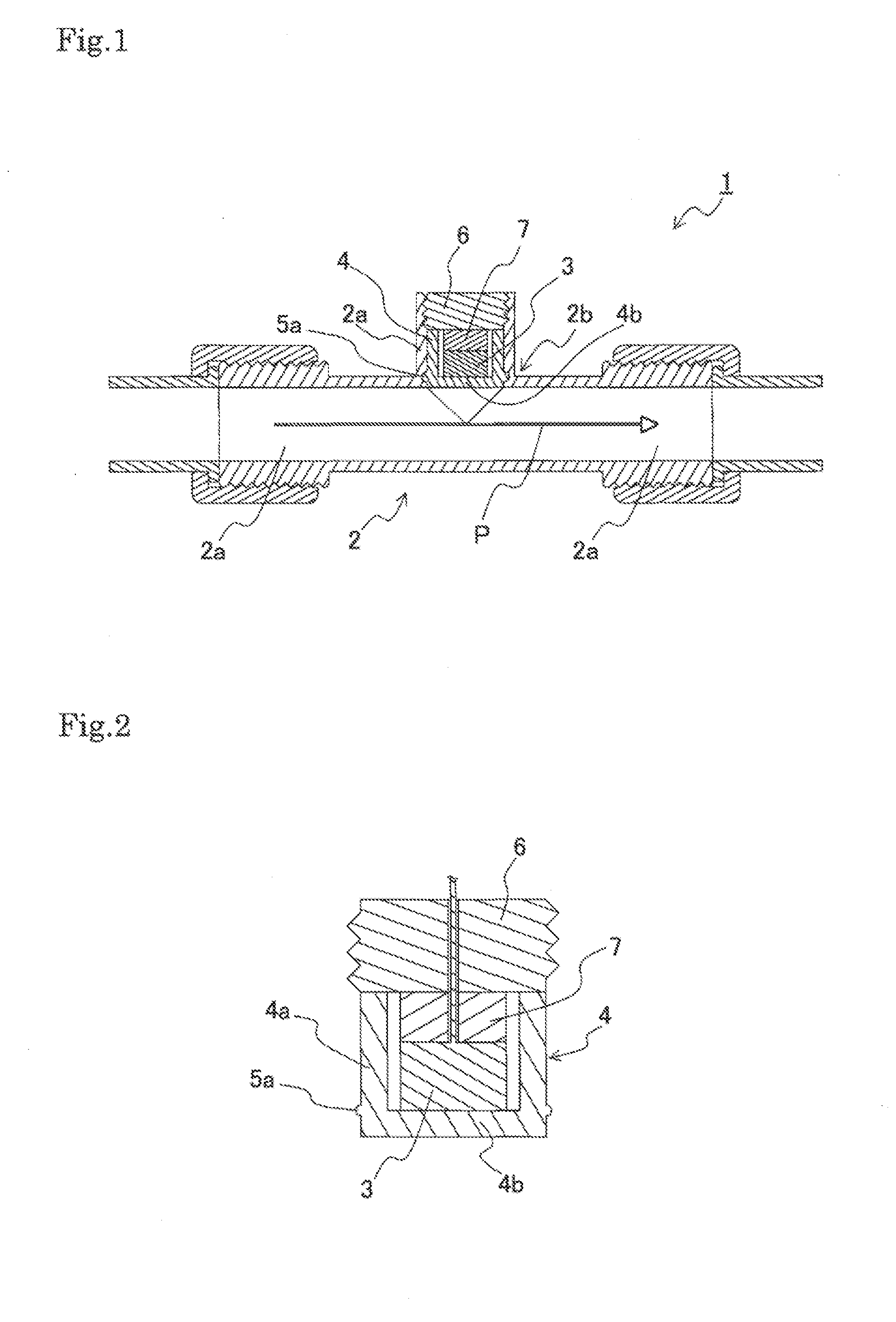
[0027]As shown in FIG. 1, a fluid measurement sensor attachment structure 1 of the present invention is configured such that a fluid measurement sensor 3 (hereinafter, may be referred to simply as a “sensor 3”) is attached to a branch pipe 2a among three or more branch pipes branched from a pipe 2, thereby measuring properties of a fluid flowing through a flow path P that is formed by remaining branch pipes 2a.

[0028]In the present invention, a “pipe 2 branched into three or more branch pipes” refers to a pipe in which branch pipes 2a extend from one point in three or more directions, and typically refers to a pipe in which branch pipes 2a can be respectively connected to other pipes as in a T-joint. However, there is no limitation to this, and the pipe 2 may be a pipe in which at least one of the branch pipes 2a has a shape suitable for attachment of the sensor 3 as shown in FIG. 1. Although not shown, the configuration also may be such that sensors 3 are arranged at two branch pip...


PUM


Abstract

The present invention provides a fluid measurement sensor attachment structure in which a fluid measurement sensor is attached to a branch pipe among three or more branch pipes branched from a pipe, thereby measuring properties of a fluid flowing through a flow path that is formed by remaining branch pipes, comprising a sleeve that can accommodate the fluid measurement sensor, wherein the sleeve is a member in a shape of a tumbler including a circumferential wall that is substantially cylindrical and a protective wall that is disposed at one end of the circumferential wall and that does not disturb a function of the sensor, a seal lip is disposed on the circumferential wall near the protective wall, and the sleeve is inserted into the branch pipe such that the protective wall is positioned near a base end of the branch pipes.

Description

BACKGROUND OF THE INVENTION[0001]1. Field of the Invention[0002]The present invention relates to a fluid measurement sensor attachment structure. More specifically, the present invention relates to a fluid measurement sensor attachment structure with which measurements can be performed at high precision without lowering a fluid transport capacity.[0003]2. Description of the Related Art[0004]Various fluid measurement sensor attachment structures have been provided in order to measure properties such as the flow rate, the fluid pressure, and the transparency of a fluid passing through a pipe. Examples thereof include an attachment structure in which a sensor is disposed in one of three branch pipes of a T-joint, and the flow rate and the like of a fluid flowing through the remaining two pipes are measured. Japanese Laid-Open Patent Publication No. 9-166512 describes that a fluid pressure sensor provided with a cylindrical sensor casing that is fitted to an inner wall of a joint base e...

Claims


Application Information

Patent Timeline
Patent Type & Authority Applications(United States)
IPC IPC(8): G01F15/18
CPCG01F1/34G01F1/662G01F1/667G01L19/0023G01F15/18G01F15/00G01D11/30G01L19/00G12B9/08
Inventor OHMIYA, JUNJIFUJII, MAKOTOKOIKE, TOMOYUKI
Owner NIPPON PILLAR PACKING CO LTD
Why Eureka
Try Eureka