Air Cooled Power Feeders for Wind Turbine Applications

Inactive Publication Date: 2013-08-22
CLIPPER WINDPOWER INC
View PDF5 Cites 17 Cited by
  • Summary
  • Abstract
  • Description
  • Claims
  • Application Information

AI Technical Summary

Problems solved by technology

However, the cost of these conductors is directly proportional to the amount of conducting material, such as copper in most cases, utilized in their construction.
Having thicker conductors thereby increases the cost of the conductors and the overall cost of cons

Method used


Image

  • Air Cooled Power Feeders for Wind Turbine Applications
  • Air Cooled Power Feeders for Wind Turbine Applications
  • Air Cooled Power Feeders for Wind Turbine Applications

Examples


Embodiment Construction

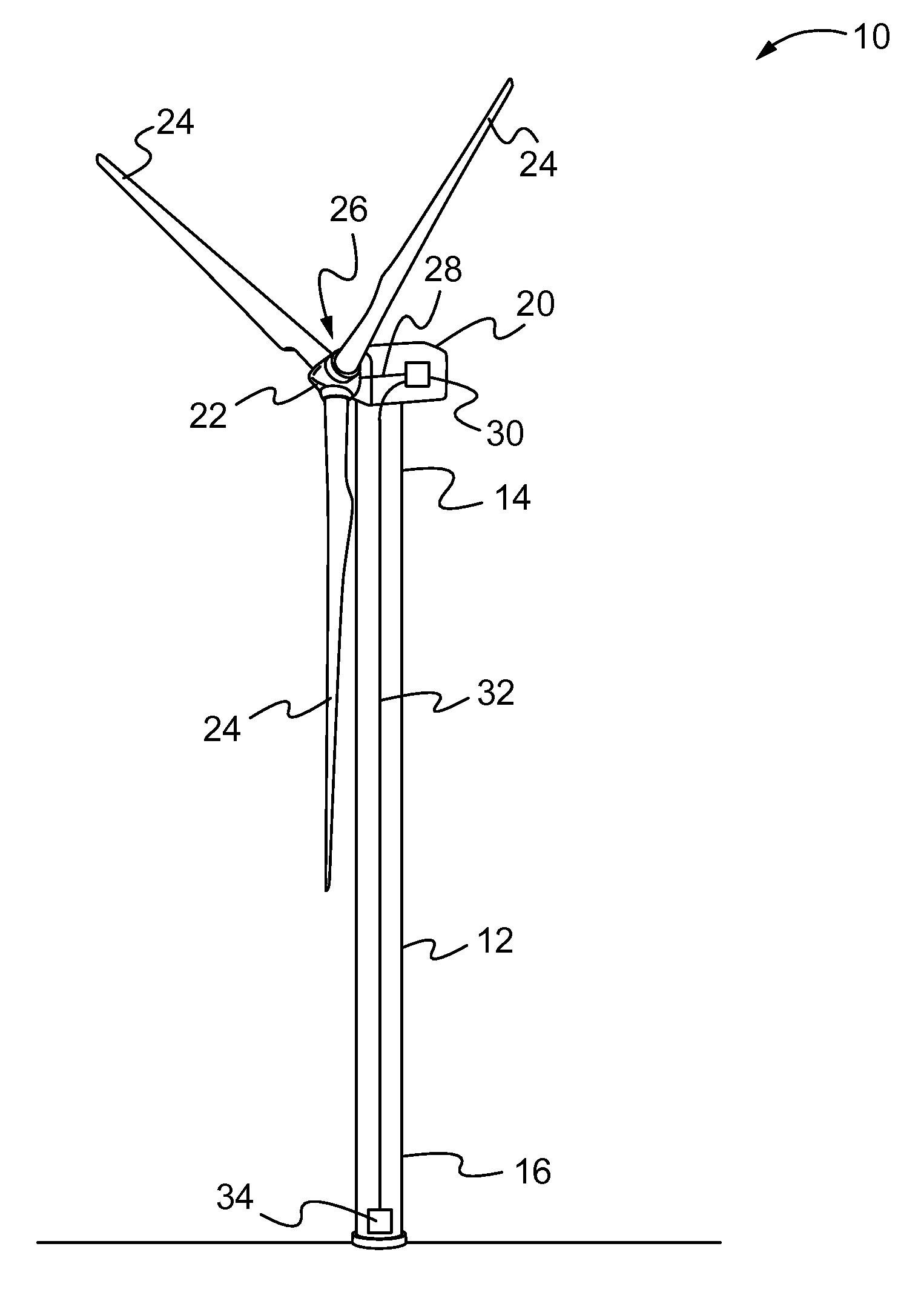
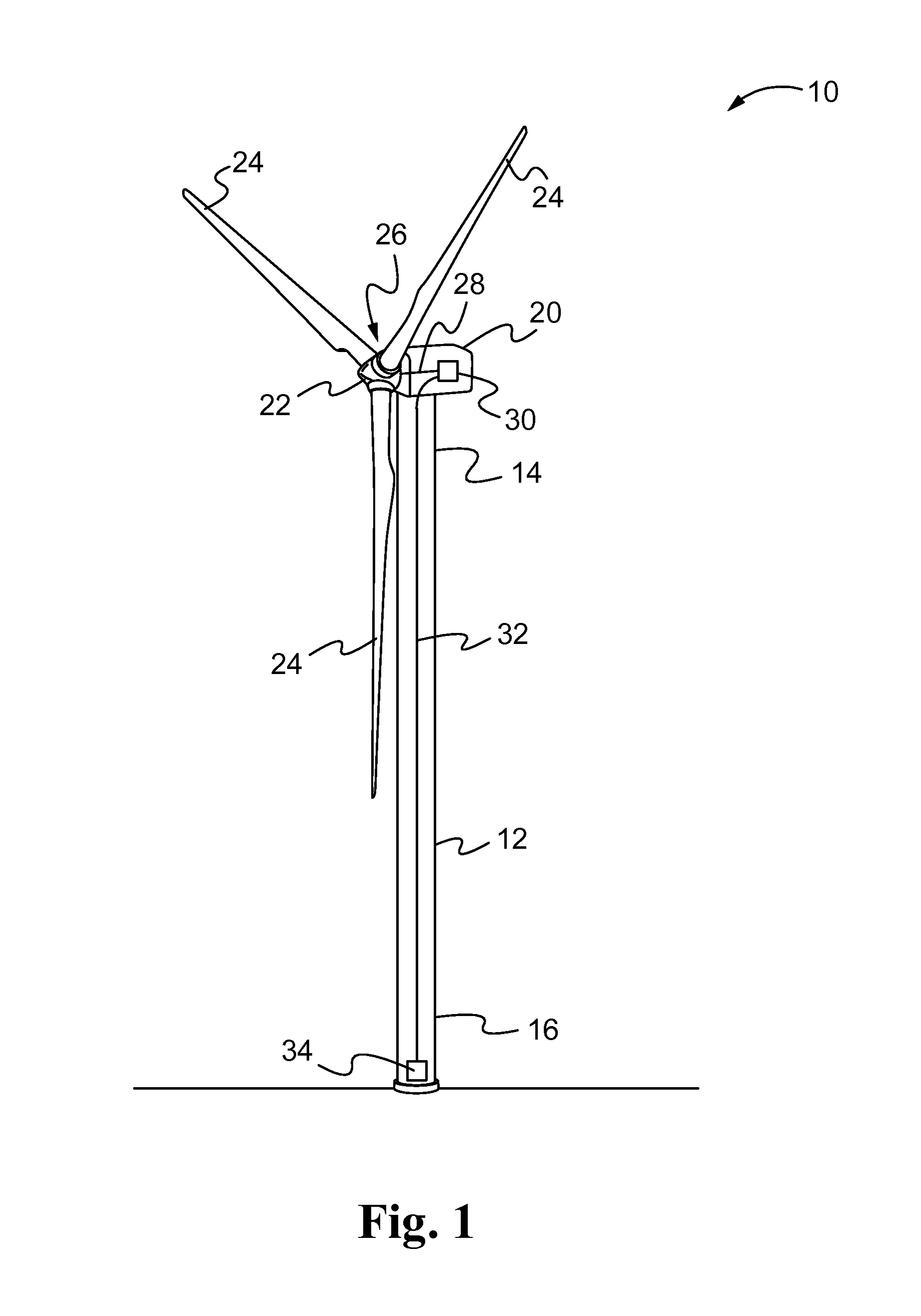
[0016]Referring now to the drawings, and with specific reference to FIG. 1, a wind turbine 10 according to one embodiment of the present disclosure is shown. While all components of the wind turbine 10 are not shown or described herein, the wind turbine 10 may include a vertically oriented tower 12. Typically, the tower 12 of a wind turbine 10 may extend upwards to a height of, including but not limited to, two hundred and forty vertical feet (240 ft.) at which the wind turbine 10 can optimally capture the kinetic energy of the wind. Other heights are certainly possible. The tower 12 may have a top 14, and a base 16.

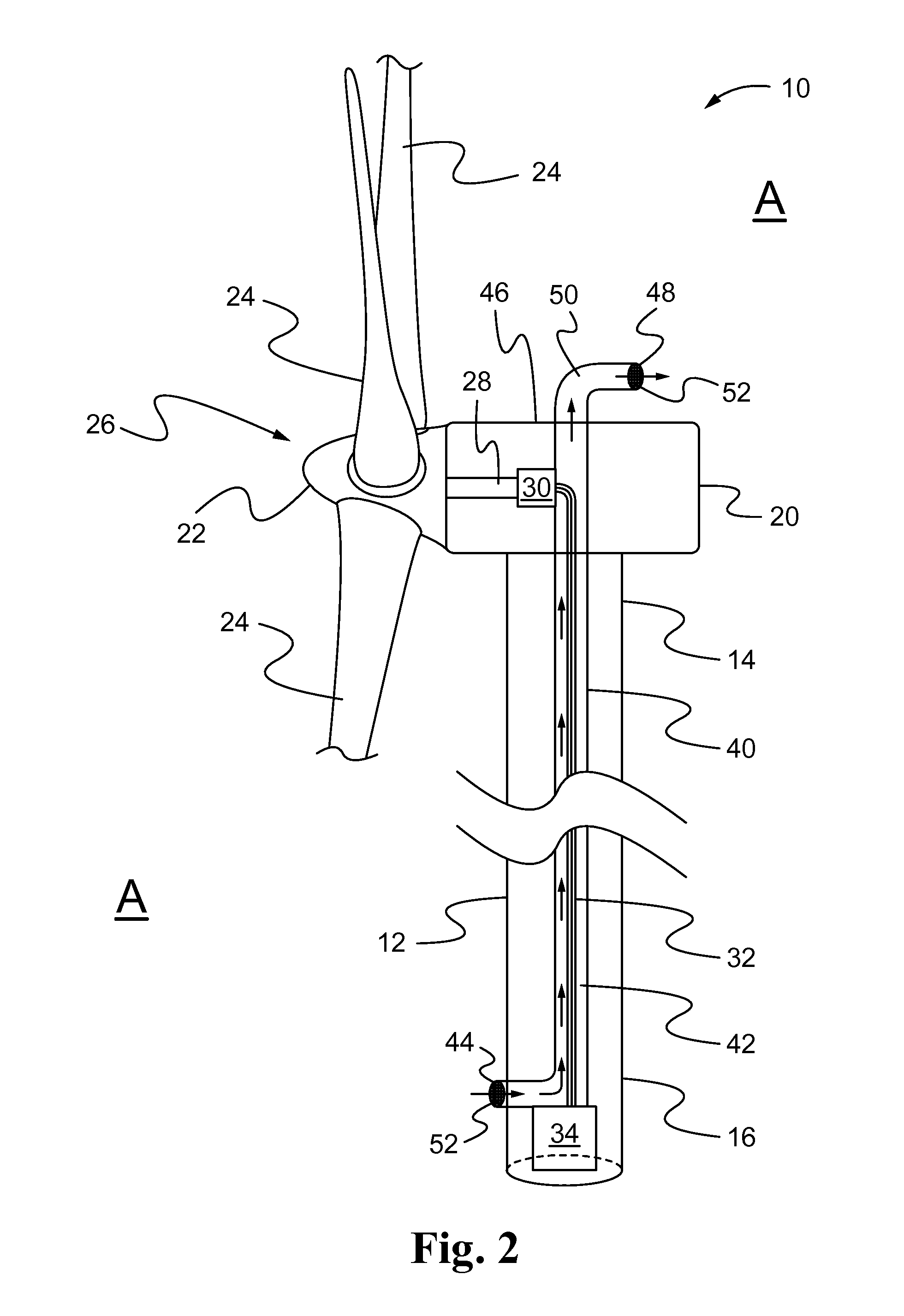
[0017]A nacelle 20 may be rotatably mounted at the top 14 of the tower 12 with a hub 22 mounted for rotation to the nacelle 20. Radially extending from the hub 22 are a plurality of blades 24. Together, the hub 22 and blades 24 are referred to as the rotor 26. The rotor 26 may be mounted to a main shaft 28 within the nacelle 20. The main shaft 28 is operatively connected...


PUM


Abstract

A wind turbine is disclosed. The wind turbine may comprise a tower having a top and a base, a generator located near the top of the tower, a main shaft operatively connected to the generator, a hub operatively connected to the main shaft, a plurality of blades extending from the hub, and at least one electrical conductor connected to the generator, the conductor configured to carry electric power from the generator to the base of the tower. The wind turbine may further comprise a conduit enclosing the conductor with the conduit having a lower air inlet opening and an upper air outlet opening. The conduit removes heat generated by the conductor by inducing a chimney effect, causing the heat of the conductor to rise up the conduit and out of the tower through the upper air outlet opening, while drawing in air from outside the tower through the lower air inlet opening.

Description

TECHNICAL FIELD[0001]The present disclosure relates generally to wind turbines and, more particularly, to mechanisms for cooling components of a wind turbine.BACKGROUND[0002]In recent years, wind turbines have been integrated into electric power generation systems to create electricity to support the needs of both industrial and residential applications. Such wind turbines capture the kinetic energy of the wind and convert it into electricity. A typical wind turbine includes a set of two or three large blades mounted to a hub. Together, the blades and hub are referred to as the rotor. The rotor is connected to a main shaft, which in turn, is connected to a generator. When the wind causes the rotor to rotate, the kinetic energy of the wind is captured and converted into rotational energy. The rotational energy of the rotor is translated along the main shaft to the generator, which then converts the rotational energy into electricity. The electricity produced by the wind turbine is th...

Claims


Application Information

Patent Timeline
IPC IPC(8): F03D9/00H02G5/10
CPCH02B1/56H02G3/03F03D11/0066Y02E10/725Y02E10/722Y02E10/465F05B2260/20F03D80/60F03D80/85H02G5/10Y02E10/46Y02E10/72
Inventor HIMMELMANN, RICHARD A.
Owner CLIPPER WINDPOWER INC
Why Eureka
Try Eureka