System And Method For Antenna Pattern Estimation

a technology of antenna pattern estimation and system, applied in the direction of antenna radiation diagram, antenna, electrical equipment, etc., can solve the problems of cost and inefficiency of scanning a known antenna over the antenna under tes

Active Publication Date: 2013-08-22
SRC INC
View PDF5 Cites 19 Cited by
  • Summary
  • Abstract
  • Description
  • Claims
  • Application Information

AI Technical Summary

Benefits of technology

[0015]Although the inverse source problem is unsolvable in full generality, it is solvable if the configurations of radiating and passive structures are known to be constrained. In particular, a solution of the inverse source problem would infer a volumetric current distribution from extensive pattern measurements. Both current distributions and radiation patterns are described by infinite dimensional vector spaces and this leads to nonuniqueness. The design spaces proposed by the present invention have the distinct adv...

Problems solved by technology

The cost and inefficiency of scanning a known antenna over the antenna under test was mentioned above.
Both current ...

Method used


Image

  • System And Method For Antenna Pattern Estimation
  • System And Method For Antenna Pattern Estimation
  • System And Method For Antenna Pattern Estimation

Examples


Embodiment Construction

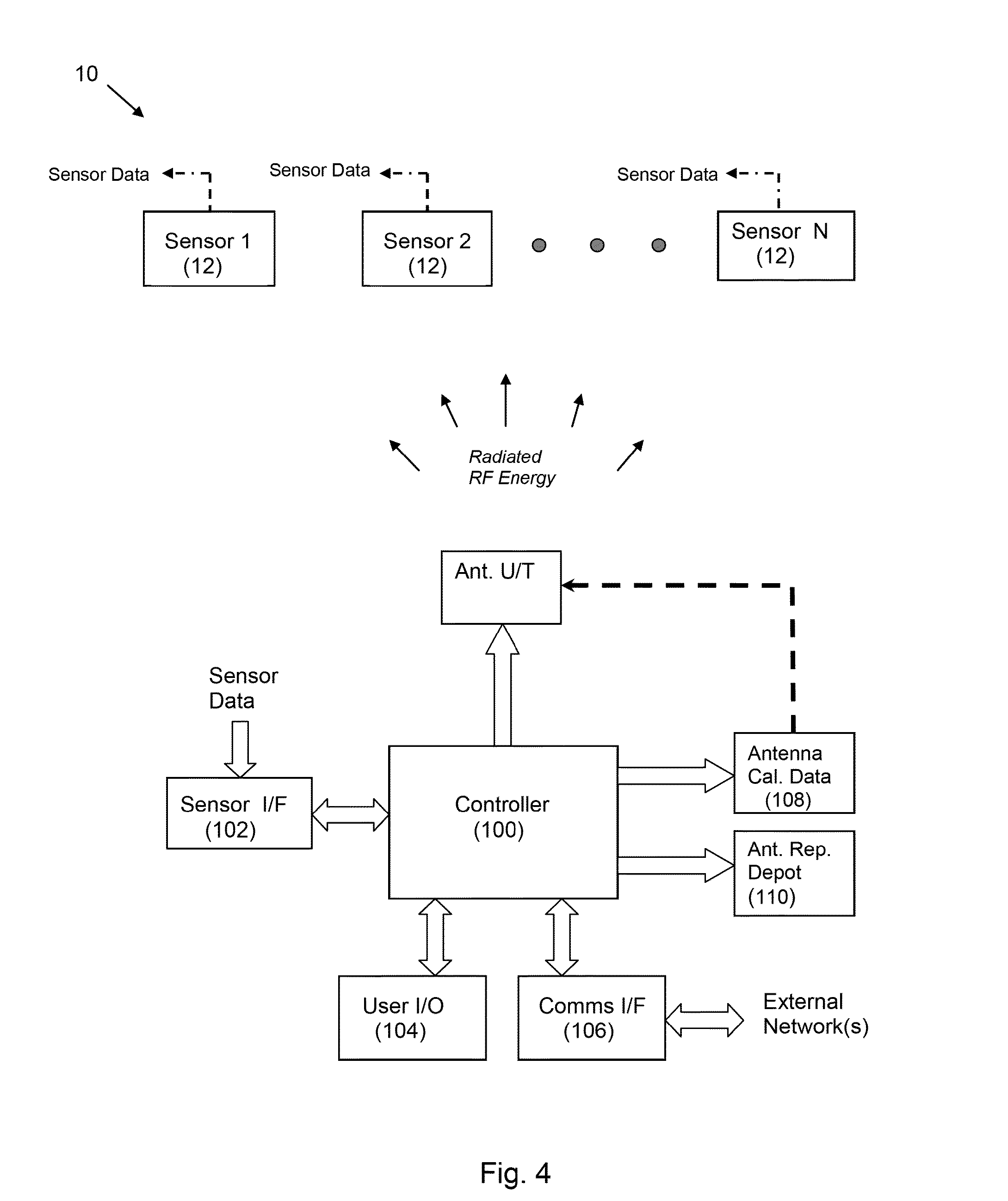
[0034]Reference will now be made in detail to the present exemplary embodiments of the invention, examples of which are illustrated in the accompanying drawings. Wherever possible, the same reference numbers will be used throughout the drawings to refer to the same or like parts. An exemplary embodiment of the system of the present invention is shown in FIG. 4, and is designated generally throughout by reference numeral 10.

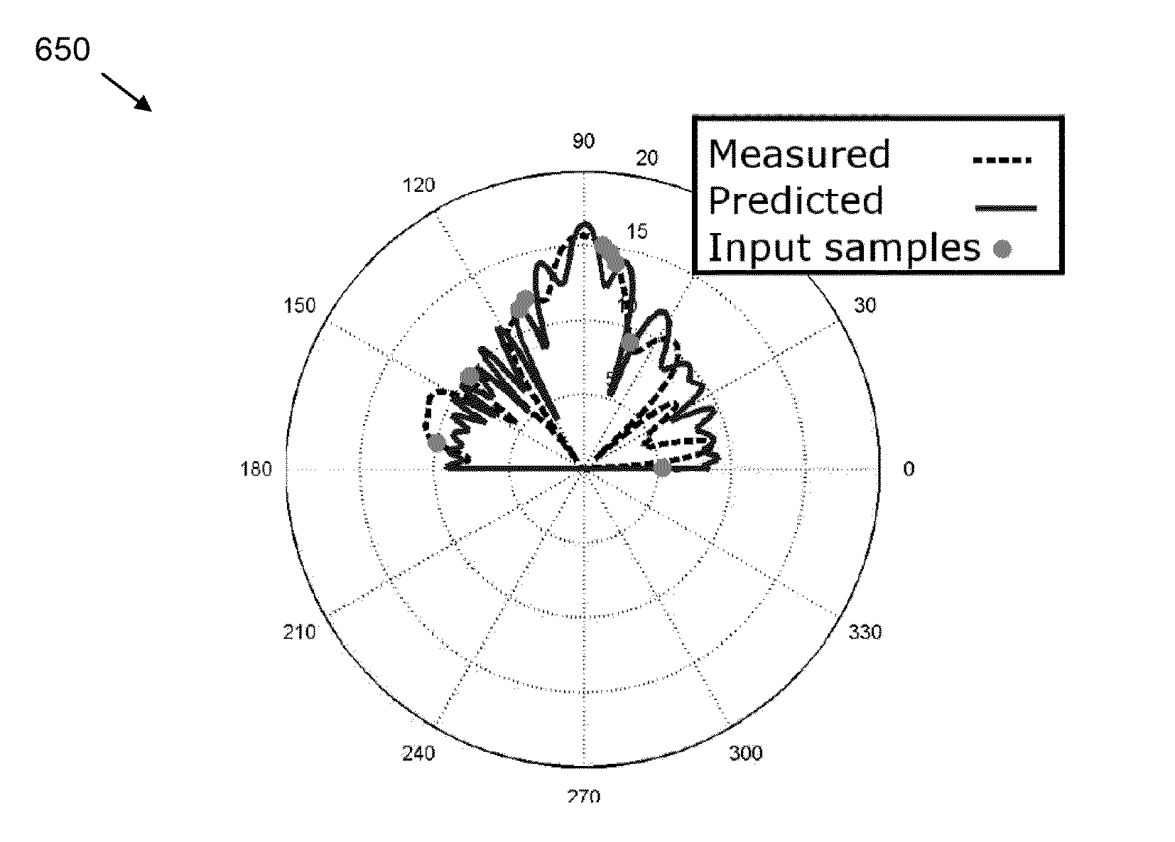
[0035]Before describing the system and method of the present invention, the general theory that permits extrapolation of antenna patterns is developed herein. The approach of the present invention relies on the fact that when enough pattern measurements are taken, the radiating structure of the antenna is completely constrained. Given this radiating structure, we can extrapolate the directivity at any location. Of course, a crucial point is that it takes finitely many parameters to specify a particular antenna in a class of possible designs.

[0036]Formally speaking...


PUM


Abstract

The present invention is directed to a system and method for extrapolating antenna radiation patterns from a small number of measurements. The present invention is configured to derive an initial estimate based on design information and compare the initial estimate to far-field measurements. The controller is configured to recursively obtain a final estimate wherein a difference between the far-field measurements and the final estimate is less than a predetermined amount. The final estimate represents an extrapolated mapping of the antenna pattern.

Description

CROSS-REFERENCE TO RELATED APPLICATIONS[0001]This application claims priority to U.S. Provisional Patent Application Ser. No. 61 / 599,633 filed on Feb. 16, 2012, the content of which is relied upon and incorporated herein by reference in its entirety, and the benefit of priority under 35 U.S.C. §119(e) is hereby claimed.BACKGROUND OF THE INVENTION[0002]1. Field of the Invention[0003]The present invention relates generally to antenna measurement systems, and particularly to a system for estimating antenna patterns using far field samples.[0004]2. Technical Background[0005]An antenna is an electrical transducer that converts an electrical signal into a radio frequency (RF) signal, and vice versa. An antenna is used in conjunction with a radio transmitter or radio receiver. For example, when a radio station transmits a signal (e.g., music), the signal is provided to a radio transmitter that amplifies and conditions the signal before providing it to the antenna. The transmitter “excites”...

Claims


Application Information

Patent Timeline
IPC IPC(8): G01R29/10
CPCG01R29/10H01Q3/267
Inventor ROBINSON, MICHAEL
Owner SRC INC
Why Eureka
Try Eureka