Automatic Signal, SAR, and HAC Adjustment with Modal Antenna Using Proximity Sensors or Pre-defined Conditions

Active Publication Date: 2013-05-23
KYOCERA AVX COMPONENTS (SAN DIEGO) INC
View PDF5 Cites 14 Cited by
  • Summary
  • Abstract
  • Description
  • Claims
  • Application Information

AI Technical Summary

Benefits of technology

[0011]A method has been derived to dynamically sample near-field properties derived from proximity sensors or other sensors integrated into a mobile device and modify the antenna radiation pattern to improve communication link quality along with near-field parameters such as SAR. An algorithm and look-up table containing pre-measured electrical parameters to include TRP, TIS, and SAR are developed and integrated with hardware which includes an antenna and active components to dynamically modify the radiation pattern of the a

Problems solved by technology

SAR tends to increase with increasing TRP, as well as interference which will cause HAC to fail to meet requiremen

Method used


Image

  • Automatic Signal, SAR, and HAC Adjustment with Modal Antenna Using Proximity Sensors or Pre-defined Conditions
  • Automatic Signal, SAR, and HAC Adjustment with Modal Antenna Using Proximity Sensors or Pre-defined Conditions
  • Automatic Signal, SAR, and HAC Adjustment with Modal Antenna Using Proximity Sensors or Pre-defined Conditions

Examples


Embodiment Construction

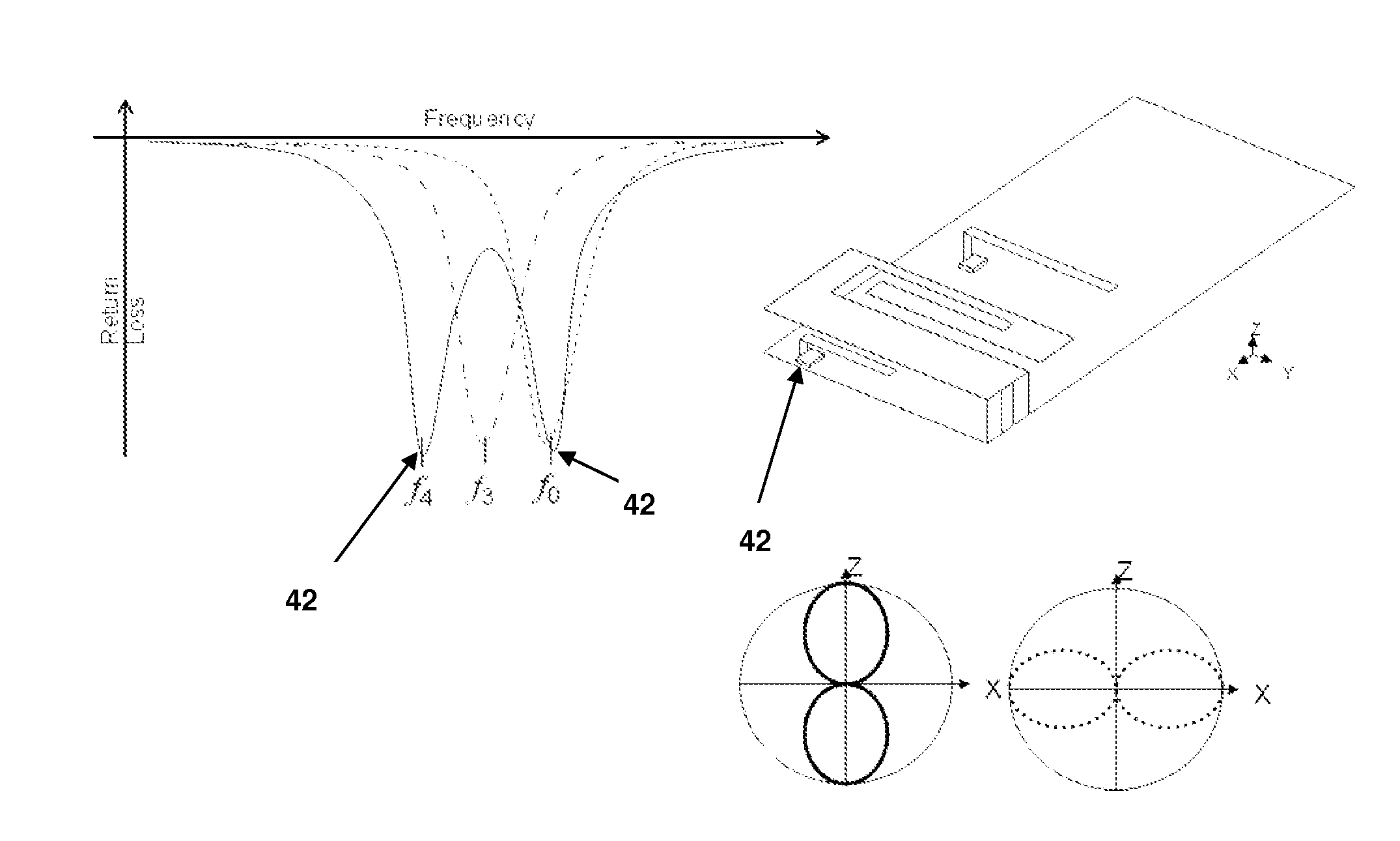
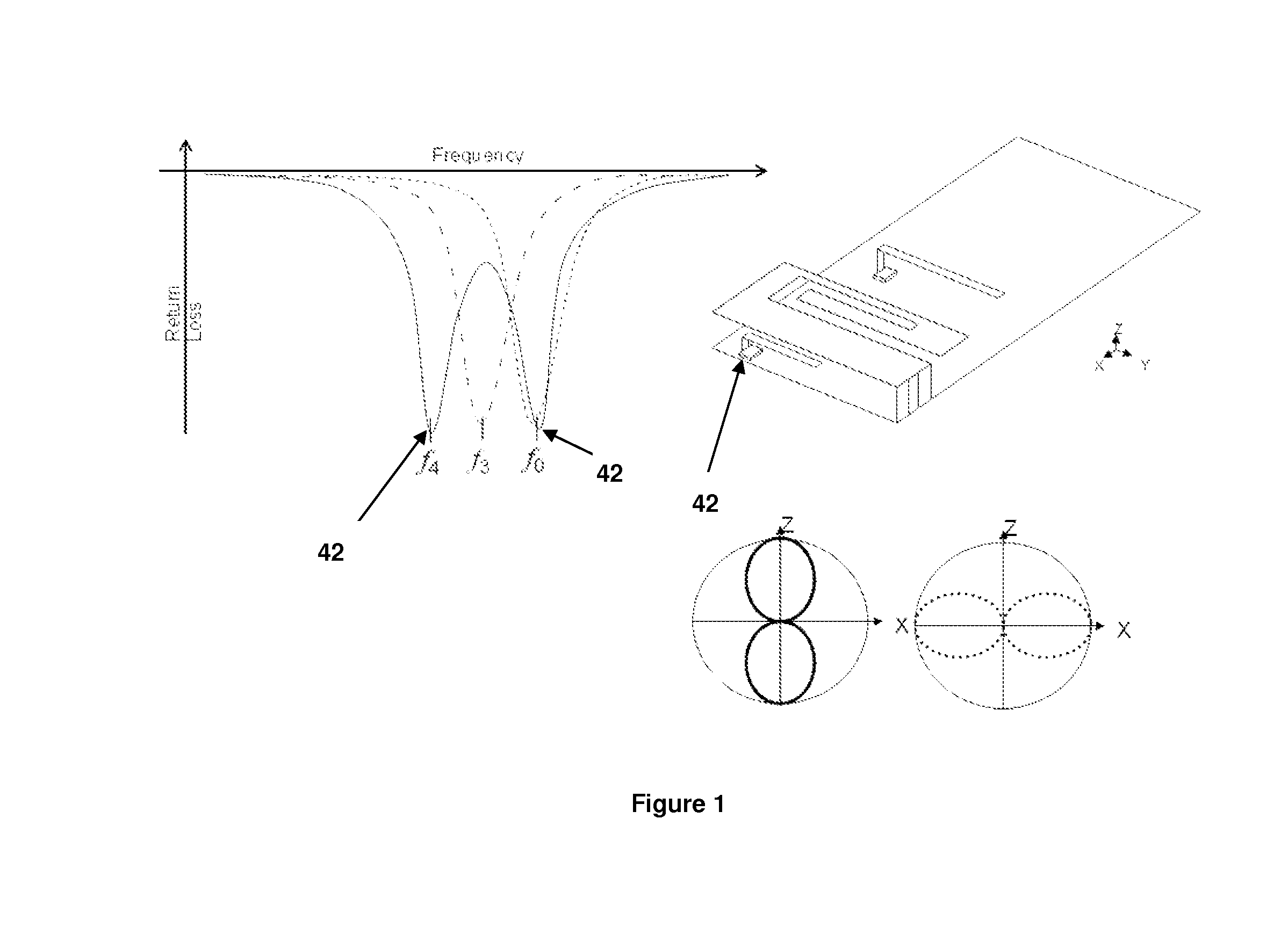
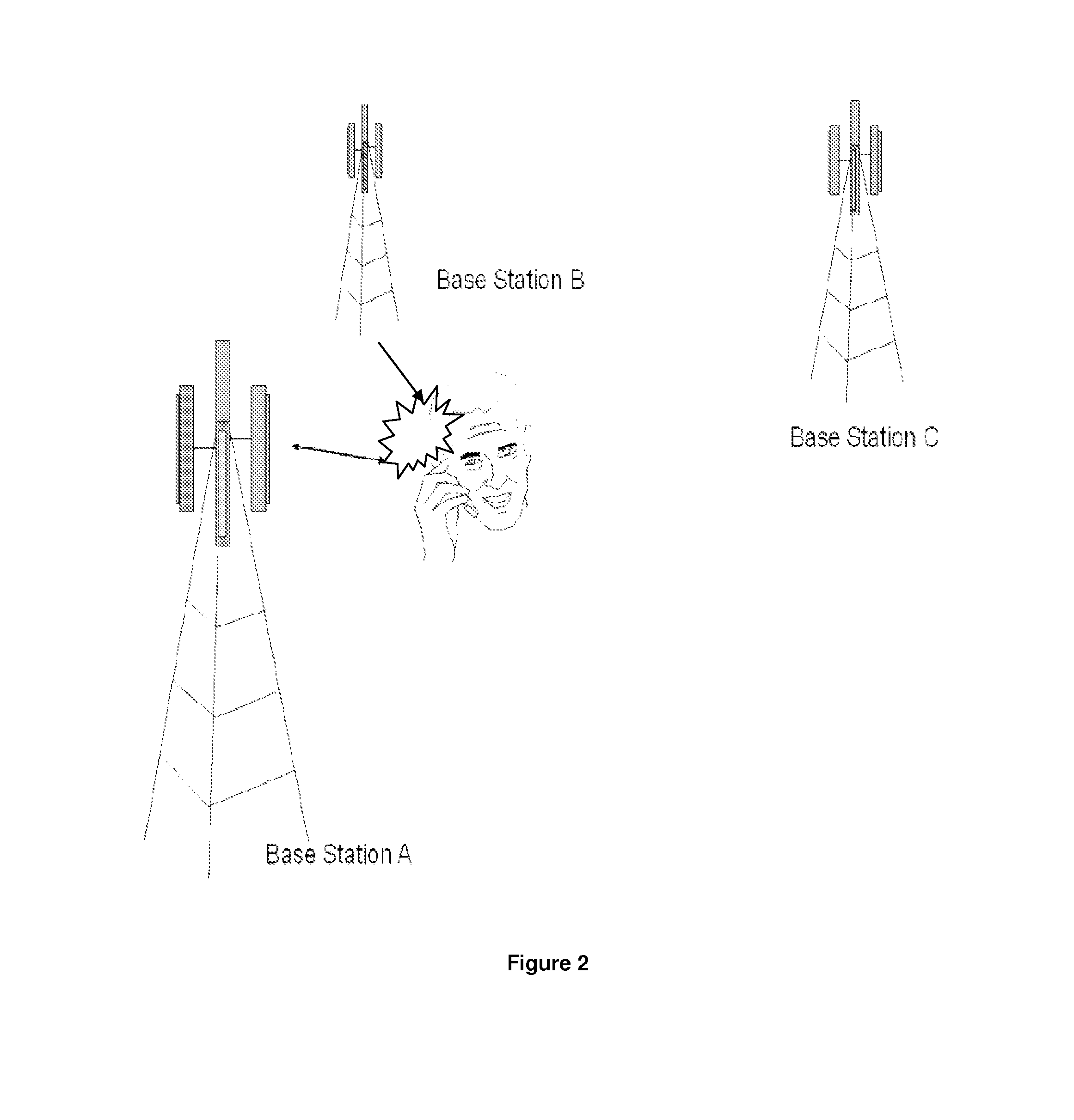
[0023]The antenna systems and methods described herein utilize a beam steering technique to reduce interference from one or multiple sources. A platform has been derived to increase the link budget based on the modification of the antenna radiation pattern and is, in part, based upon U.S. Ser. No. 12 / 043,090, filed Mar. 05, 2008, titled “ANTENNA AND METHOD FOR STEERING ANTENNA BEAM DIRECTION”, which issued as U.S. Pat. No. 7,911,402 on Mar. 22, 2011, hereinafter “the '402 patent”; the contents of which are hereby incorporated by reference. The '402 patent describes a modal adaptive antenna system, which uses an antenna radiation pattern beam steering technique to improve communication link quality between the mobile wireless device and the base terminal. This technique provides an antenna with multiple radiation pattern states along with an algorithm to dynamically sample link performance and adjust the radiation pattern of the mobile antenna to improve communication link quality. T...


PUM


Abstract

A modal adaptive antenna system that dynamically samples proximity sensors or other sensors to determine the use case for the wireless device and then adjust the antenna radiating mode to optimize communication link performance. The modal adaptive antenna system is capable of modifying the antenna radiation pattern to improve communication link quality along with near-field parameters such as SAR and HAC. An algorithm and look-up table containing pre-measured electrical parameters to include TRP, TIS, and SAR are developed and integrated with hardware which includes an antenna and active components to dynamically modify the radiation pattern of the antenna as well as proximity sensors and or other sensing devices.

Description

CROSS-REFERENCE TO RELATED APPLICATIONS[0001]This application is a continuation-in-part (CIP) of commonly owned U.S. Ser. No. 13 / 029,564, filed Feb. 17, 2011, titled “ANTENNA AND METHOD FOR STEERING ANTENNA BEAM DIRECTION”; which in turn claims priority to:[0002]U.S. Ser. No. 12 / 043,090, filed Mar. 05, 2008, titled “ANTENNA AND METHOD FOR STEERING ANTENNA BEAM DIRECTION”, issued as U.S. Pat. No. 7,911,402 on Mar. 22, 2011;[0003]the contents of each of which are hereby incorporated by reference.BACKGROUND OF THE INVENTION[0004]1. Field of the Invention[0005]This invention relates generally to the field of wireless communication. In particular, this invention relates to antenna systems and methods for optimizing communication link quality with intended transceivers.[0006]2. Description of the Related Art[0007]As new generations of handsets, gateways, and other wireless communication devices become embedded with more applications and the need for bandwidth becomes greater, new antenna ...

Claims


Application Information

Patent Timeline
IPC IPC(8): H01Q25/04
CPCH01Q25/04H01Q9/0421H01Q3/00H01Q1/243
Inventor DESCLOS, LAURENTMATSUMORI, BARRYROWSON, SEBASTIANSHAMBLIN, JEFFREY
Owner KYOCERA AVX COMPONENTS (SAN DIEGO) INC
Why Eureka
Try Eureka