Directional diagram reconstructed microstrip antenna with ring-shaped groove of

A technology of microstrip antenna and pattern, applied in the field of electronics, can solve problems such as difficult carrier conformality, achieve high practical value, small antenna size, and convenient effect

Inactive Publication Date: 2005-03-23
UNIV OF ELECTRONICS SCI & TECH OF CHINA
View PDF0 Cites 12 Cited by
  • Summary
  • Abstract
  • Description
  • Claims
  • Application Information

AI Technical Summary

Problems solved by technology

But the disadvantage is that the wire antenna s

Method used


Image

  • Directional diagram reconstructed microstrip antenna with ring-shaped groove of
  • Directional diagram reconstructed microstrip antenna with ring-shaped groove of
  • Directional diagram reconstructed microstrip antenna with ring-shaped groove of

Examples


Embodiment Construction

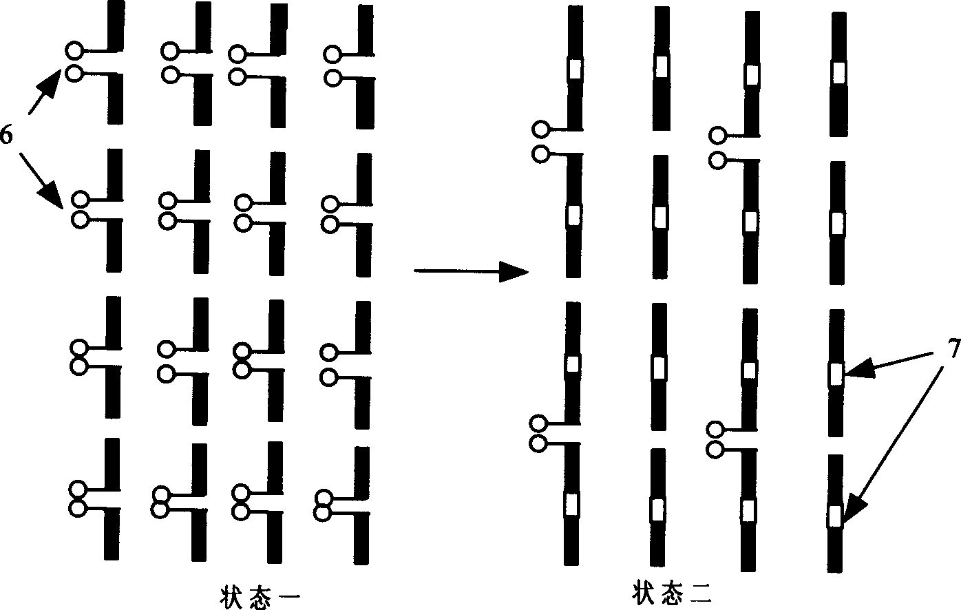
[0026] exist Figure 6 In the embodiment, the size and material properties of the antenna are: the metal base plate 12 and the metal patch 14 adopt copper foil with a thickness of 0.018mm; the size of the metal base plate 12 is 34×34mm 2 ; The small rectangular metal patch 15 is 2×2mm 2 ; The inner size of the rectangular metal conduction band 16 is 4 × 4mm 2 , the outer dimension is 6×6mm 2 ; The inner size of the rectangular metal conduction band 17 is 8×8mm 2 , the outer dimension is 10×10mm 2 ; The inner size of the rectangular metal conduction belt 18 is 12×12mm 2 , the outer dimension is 14×14mm 2 ; The thickness of the dielectric substrate 13 is 3mm, and the size is 34×34mm 2 , the relative permittivity is 3.5; the size of the microelectromechanical switch (MEMS) (19~30) is 0.25×1mm 2 . The six microelectromechanical switches 19, 24, 25, 26, 29 and 30 on the left are in the connected state, and the six microelectromechanical switches 20, 21, 22, 23, 27 and 28 on...


PUM


Abstract

The invention provides a direction graph reconfigurable microstrip antenna with ring channel. It adopts the structure of the microstrip rectangle patch antenna. Make several ring channels with different perimeters on the rectangle patch antenna to form a metal patch 14 with new structure, connect the adjoint ring conduction bands or connect the ring conduction band with the small rectangle patch 15 in the middle through the microcomputer electric switches, change the current distribution on the whole metal patch 14 by means of changing the operating states of the microcomputer electric switches (19-30) and then can obtain antenna radiation direction graphs with different main lobe points of the same plane at the same frequency point. Adopting the metal patch 14 realizes the planarization of the antenna and makes the aims of small antenna volume; light weight and easy conformation with the carriers (such as planes) come true. The antenna has simple structure and high use value.

Description

Technical field [0001] The invention belongs to the field of electronic technology, and particularly relates to the microstrip slotted patch antenna technology with a micro-electromechanical switch (MEMS). Background technique [0002] At present, there have been many researches devoted to the realization of antenna radiation pattern scanning, but there are still various problems. [0003] In many technical books about antennas, such as "ANTENNA THEORY AND DESIGN" (edited by Warren L. STUTZMAN and Gary A. Thiele), phased array antennas are mentioned, which have been widely used. It obtains antenna radiation patterns with different orientations by changing the phase relationship between each antenna array element. But this kind of antenna needs a lot of phase shifters, and the loss increases with the increase of frequency, and the antenna array cannot be made small, and it takes up a lot of space. [0004] A structurally reconfigurable antenna is described in the document "...

Claims


Application Information

Patent Timeline
IPC IPC(8): H01Q1/38H01Q13/08
Inventor 王秉中吴炜霞孙树辉
Owner UNIV OF ELECTRONICS SCI & TECH OF CHINA
Why Eureka
Try Eureka