Broadband low-profile helical antenna with loaded parasitic patch

A helical antenna and parasitic patch technology, which is applied to antennas, loop antennas, antenna grounding devices, etc., can solve the problems of small antenna gain, irrelevant axial symmetry, and high profile height.

Inactive Publication Date: 2015-07-29
SHENZHEN UNIV
View PDF3 Cites 14 Cited by
  • Summary
  • Abstract
  • Description
  • Claims
  • Application Information

AI Technical Summary

Problems solved by technology

[0010] In view of the above-mentioned deficiencies in the prior art, the object of the present invention is to provide a wide-band low-profile helical antenna loaded with parasitic patches, which solves the problem that the profile height of the wide-

Method used


Image

  • Broadband low-profile helical antenna with loaded parasitic patch
  • Broadband low-profile helical antenna with loaded parasitic patch
  • Broadband low-profile helical antenna with loaded parasitic patch

Examples


Embodiment Construction

[0035] The present invention provides a wide-band low-profile helical antenna loaded with parasitic patches. In order to make the purpose, technical solution and effect of the present invention clearer and clearer, the present invention will be further described in detail below with reference to the accompanying drawings and examples. It should be understood that the specific embodiments described here are only used to explain the present invention, not to limit the present invention.

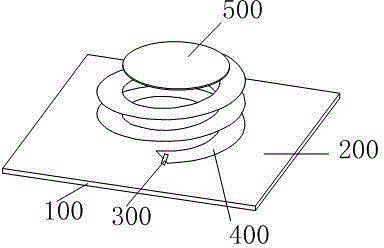
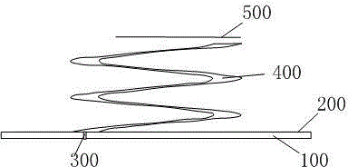
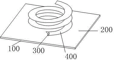
[0036] See also Figure 1a and Figure 1b , Figure 1a It is a schematic structural diagram of a preferred embodiment of a broadband low-profile helical antenna loaded with a parasitic patch according to the present invention, Figure 1b It is a side view of a preferred embodiment of the broadband low-profile helical antenna loaded with parasitic patches according to the present invention. The broadband low-profile helical antenna loaded with parasitic patches includes:

[0037] Dielectric sub...


PUM

PropertyMeasurementUnit
Widthaaaaaaaaaa
Thicknessaaaaaaaaaa

Abstract

The invention discloses a broadband low-profile helical antenna with a loaded parasitic patch. The broadband low-profile helical antenna with the loaded parasitic patch comprises a dielectric substrate, a metal grounding plate and a coaxial feed device, wherein the metal grounding plate is printed on the dielectric substrate, the outer surface of the coaxial feed device is connected with the grounding plate, an inner core of the coaxial feed device is connected with the bottom of a spiral metal piece, and a metal patch used for enhancing electromagnetic coupling with the spiral metal piece is arranged above the spiral metal piece. According to the broadband low-profile helical antenna with the loaded parasitic patch, a parasitic metal patch is loaded on the spiral metal piece in an electromagnetic coupling mode so that performances of a patch helical antenna can be effectively improved, profile height of the antenna is reduced, and meanwhile, symmetry of antenna radiation pattern in whole working bandwidth can be improved.

Description

technical field [0001] The invention relates to the technical field of antennas, in particular to a wide-band low-profile helical antenna loaded with parasitic patches. Background technique [0002] With the development of the wireless communication industry, radio frequency technology has also begun to attract more and more attention from people and industries. In the development of radio frequency technology, the antenna has always played the most important role. As a wireless signal receiving and transmitting device, the performance of the antenna has always been a very important indicator. Therefore, it is a problem to be solved to continuously improve the performance of the antenna to meet the actual use requirements. [0003] From the perspective of polarization, antennas are divided into linearly polarized antennas and circularly polarized antennas. Comparing the two, the reliability of circularly polarized antennas is particularly prominent, even in complex environ...

Claims


Application Information

Patent Timeline
IPC IPC(8): H01Q1/38H01Q1/36H01Q1/48H01Q1/50H01Q7/00
Inventor 唐锡辉廖志成
Owner SHENZHEN UNIV
Why Eureka
Try Eureka