
MIMO system and method of generating hierarchical codebook therefor

a multi-input multiple output and codebook technology, applied in the field of multi-input multiple output (mimo) system and the method of generating hierarchical codebooks therefor, can solve the problems of increasing calculation complexity, degrading efficiency, and reducing the performance of spatially correlated channels

Active Publication Date: 2013-08-22
SEOUL NAT UNIV R&DB FOUND
View PDF5 Cites 6 Cited by
  • Summary
  • Abstract
  • Description
  • Claims
  • Application Information

AI Technical Summary

Benefits of technology

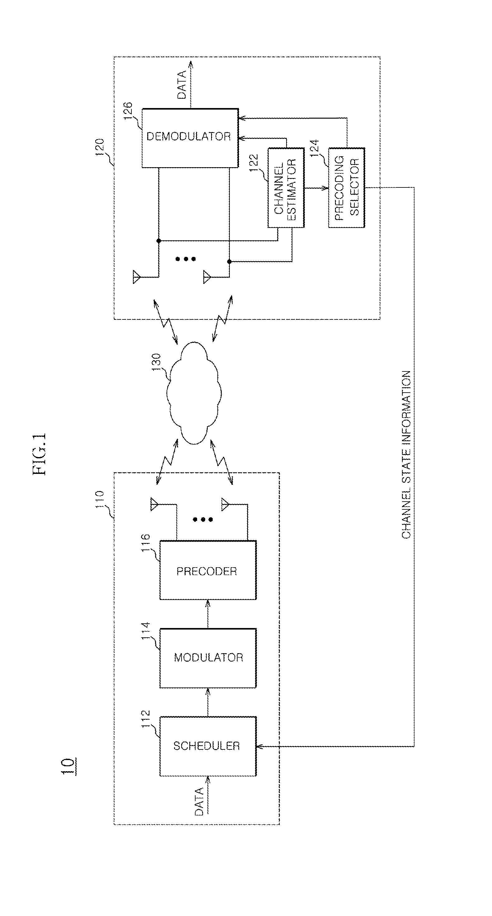
The present invention relates to a multi-antenna system and a method for generating a codebook for the system. In one embodiment, the system includes a transmitting end with a hierarchical codebook and a scheduler for selecting precoding matrices based on channel state information. The precoder applies the selected matrices to data to be transmitted through multiple antennas. In another embodiment, a method for generating the codebook includes setting a base codebook as the upper matrix and calculating a distance between the codebooks to select a child codebook as the lower matrix. The child codebook includes a reference code and a set number of codearies with close chordal distance to the reference code. The codebook can be generated based on an LBG algorithm or other methods. The technical effects of this invention include improved signal quality and more efficient data transmission in multiple-antenna systems.

Problems solved by technology

The Grassmannian codebook has been known as being optimized for a independent identically distributed (i.i.d) channel, which leads to degraded performance in a spatially correlated channel.
However, the DFT based codebook increases calculation complexity and degrades efficiency as a size of the codebook is increased.
The DFT based codebook and the existing codebooks may reduce quantization errors as the size of the codebook is increased but may exponentially increase the calculation complexity for searching the codeword according to the size of the codebook.
However, the hierarchical codebook proposed until now is for the multi-user MIMO system and therefore, can be hardly applied to the single-user MIMO system.

Method used


Image

  • MIMO system and method of generating hierarchical codebook therefor
  • MIMO system and method of generating hierarchical codebook therefor
  • MIMO system and method of generating hierarchical codebook therefor

Examples


first embodiment

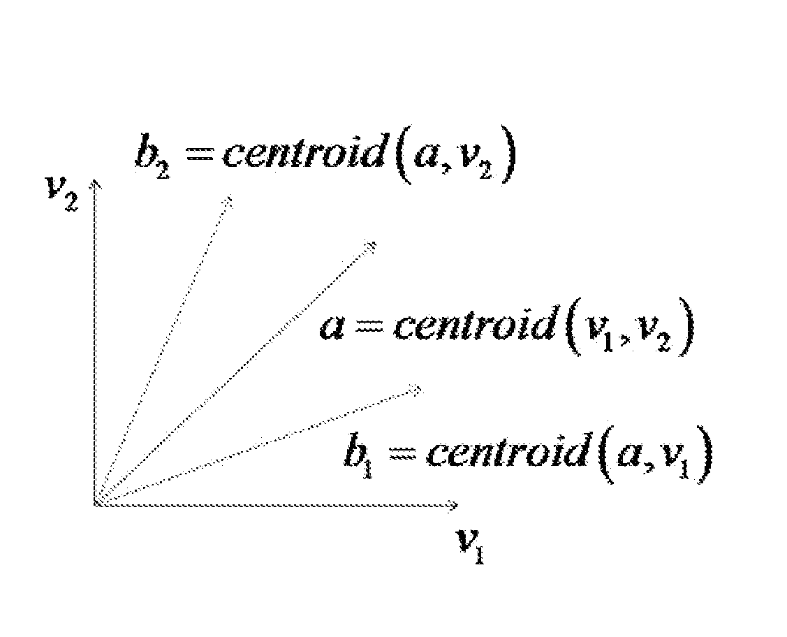
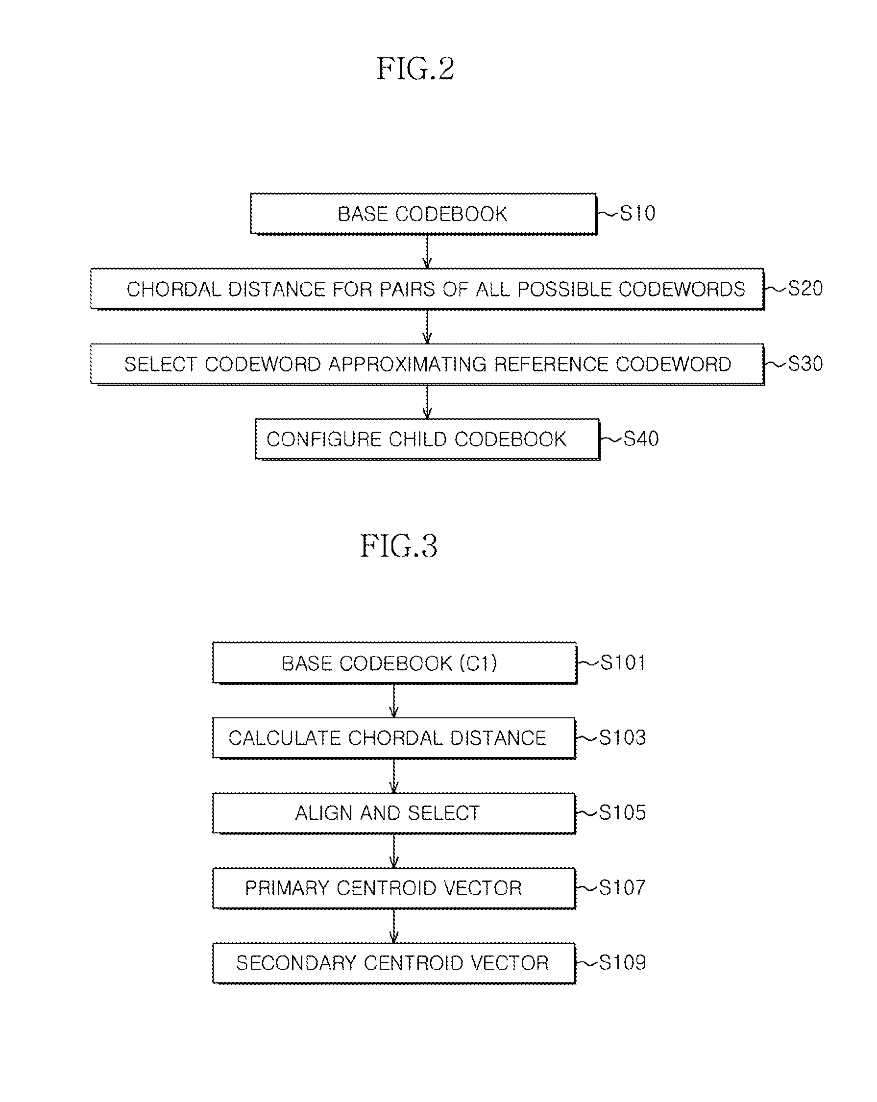
[0072]FIG. 3 is a flow chart for describing the method of generating a hierarchical codebook in accordance with the present invention and illustrates an example of the method of generating a hierarchical codebook for the i.i.d. channel.

[0073]First, for convenience of explanation, a simple system model having a single transmitting end and a single receiving end is considered. When it is assumed that the receiving end may completely estimate its own channel for a block fading channel, a system model is as follows.

y=√{square root over (P)}HHVs+n  [Equation 9]

[0074]Where P represents transmission power, H represents an M×N channel matrix in which a channel entry is i.i.d. complex Gaussian having zero average and unit dispersion, V represents an M×N precoding matrix, s represents a transmission symbol, and n represents an N×1 complex white Gaussian noise vector having the zero average and unit dispersion.

[0075]The centroid condition minimizes the mean distortion (distance) represented by...

second embodiment

[0092]FIG. 5 is a flow chart for describing the method of generating a hierarchical codebook in accordance with the present invention and illustrates another example of the method of generating a hierarchical codebook for the i.i.d. channel.

[0093]The method of generating a codebook in accordance with the second embodiment of the present invention may be represented by a codebook mapping scheme. Compared with one generating the child codebook from the base codebook in which the hierarchical codebook in accordance with the first embodiment of the present invention is the Grassmannian codebook, the child codebook is is configured based on the two codebooks that are present in advance.

[0094]Referring to FIG. 5, the first base codebook C1={v1, v2, . . . , v2B1} and the second base codebook C2={c1, c2, . . . , c2B2} are first prepared (S201). In this case, B12.

[0095]When the two base codebooks are prepared, the chordal distance between Vi(1≦i≦2B1) and cj(1≦j≦2B2) is calculated for all the...

third embodiment

[0105]FIG. 7 is a flow chart for describing the method of generating a hierarchical codebook in accordance with the present invention and illustrates an example of the method of generating a hierarchical codebook for the temporally correlated channel.

[0106]The channel state of the two consecutive time slots may be correlated by a correlation coefficient ρ in the temporally correlated channel. In the channel, the number of feedback bits may be reduced by using the channel correlation. A temporally correlated channel model is represented as follows.

H(t)=ρH(t−1)+√{square root over (1−ρ2)}G(t)  [Equation 10]

[0107]Where G(t) is the M×N matrix and each element thereof has normal distribution having the zero mean and unit distribution. ρρ is determined by an auto-correlation function of a Jake model as represented by Equation 11.

R(l)=J0(2πfDsl)  [Equation 11]

[0108]Where J0(•) is a first kind of a 0 order bezel function of type 1, fD is a Doppler shift, and Ts is a sampling time. When 1=1, ...


PUM


Abstract

Disclosed is a multiple-input multiple-output (MIMO) system including a transmitting end and a receiving end, wherein the transmitting end includes: a hierarchical codebook in which at least one base codebook is designated as the upper matrix and a child codebook generated based on a chordal distance between respective codewords configuring the base codebook is designated as the lower matrix; a scheduler configured to receive channel state information from the receiving end and select precoding matrices from the hierarchical codebook based on the channel state information; and a precoder configured to apply the precoding matrices selected in the scheduler to data to be transmitted to the receiving end and transmit the selected precoding matrices through a plurality of antennas.

Description

CROSS-REFERENCES TO RELATED APPLICATION[0001]The present application claims priority under 35 U.S.C. §119(a) to Korean application number 10-2012-0015704, filed on Feb. 16, 2013, in the Korean Intellectual Property Office, which is incorporated herein by reference in its entirety as set forth in full.BACKGROUND[0002]1. Technical Field[0003]Exemplary embodiments of the present invention relate to a wireless communication technology, and more particularly, to a multiple-input multiple-output (MIMO) system and a method of is generating a hierarchical codebook therefor.[0004]2. Related Art[0005]An example of methods for increasing data transmission efficiency in a wireless communication system may include a multiple-input multiple-output (MIMO) scheme. The MIMO scheme may be classified into a single-user MIMO (SU-MIMO) scheme and multiuser MIMO(MU-MIMO) scheme according to whether data transmission is enabled using the same resources when data are transmitted to each user.[0006]Further,...

Claims


Application Information

Patent Timeline
Patent Type & Authority Applications(United States)
IPC IPC(8): H04B15/00H04B7/04
CPCH04B7/0478H04L25/0204
Inventor LEE, JUNG WOOKO, KYEONG JUNJUNG, SUNG KYU
Owner SEOUL NAT UNIV R&DB FOUND
Learn More