Rotating device

a technology of rotating devices and rotating shafts, which is applied in the direction of bearings, shafts and bearings, rotary machine parts, etc., can solve the problems of deteriorating the properties of fluid dynamic bearings, disadvantages that may occur not only in the disk drive device, etc., and achieves the effect of enhancing any adverse effects and expanding the recording capacity of the disk drive devi

Inactive Publication Date: 2013-08-22
SAMSUNG ELECTRO MECHANICS JAPAN ADVANCED TECHNOLOGY CO LTD
View PDF8 Cites 3 Cited by
  • Summary
  • Abstract
  • Description
  • Claims
  • Application Information

AI Technical Summary

Benefits of technology

[0006]One of the methods for enlarging the recording capacity of a disk drive device is to narrow the width of a recording track and to position a magnetic head close to the surface of a magnetic recording disk. Narrowing the gap between the magnetic head and the surface of the magnetic recording disk may, however, enhance any adverse effects caused to the read / write properties of the disk drive device due to extraneous substances adhering to the surface of the magnetic recording disk.

Problems solved by technology

Considerable reduction of the amount of the lubricant may deteriorate the properties of the fluid dynamic bearing.
Such disadvantages may occur not only in the disk drive device but also in other types of rotating devices that adopt fluid dynamic bearings.

Method used


Image

  • Rotating device
  • Rotating device
  • Rotating device

Examples


first embodiment

The First Embodiment

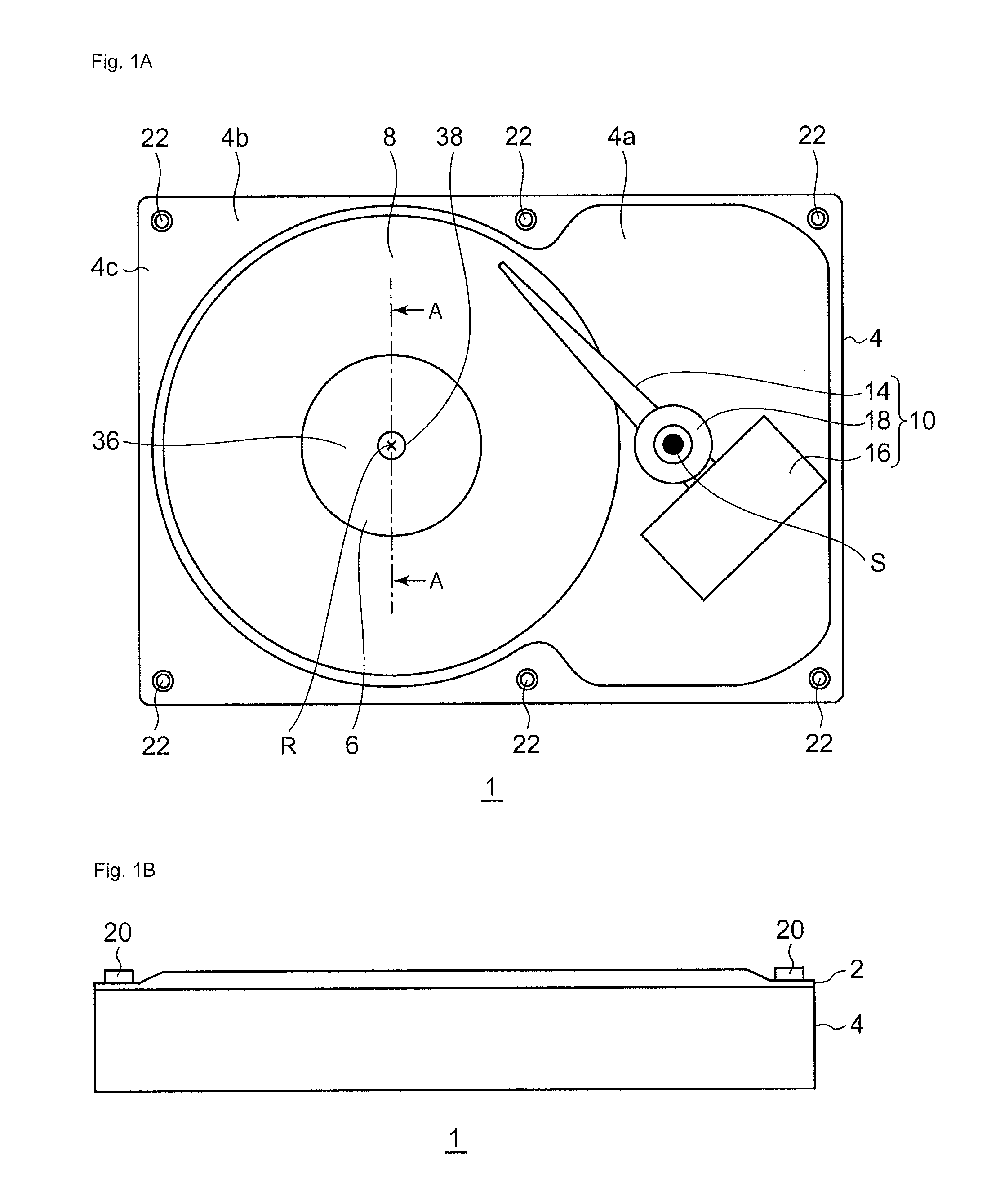
[0025]FIG. 1A and FIG. 1B are a top view and a side view, respectively, of the rotating device 1 according to the first embodiment. FIG. 1A is the top view of the rotating device 1. In FIG. 1A, the rotating device 1 is shown without a top cover 2 in order to show the inside of the rotating device 1. The rotating device 1 comprises: a base 4; a rotor 6; a magnetic recording disk 8; a data read / write unit 10; and the top cover 2.

[0026]Hereinafter, it is assumed that the side of the base 4 on which the rotor 6 is installed is the “upper” side.

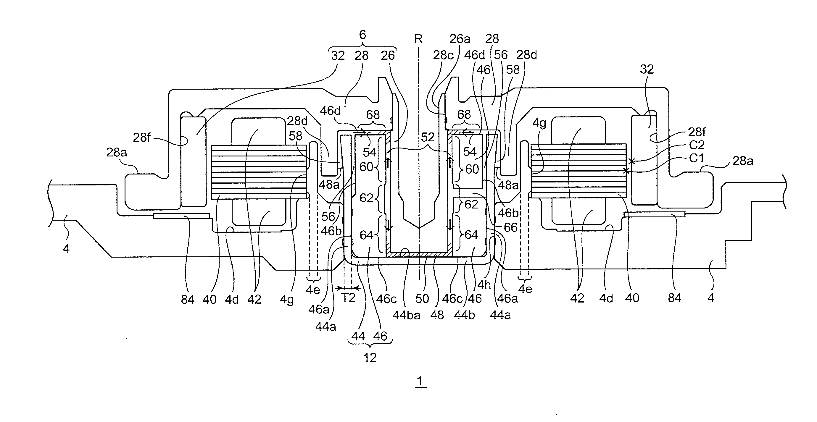
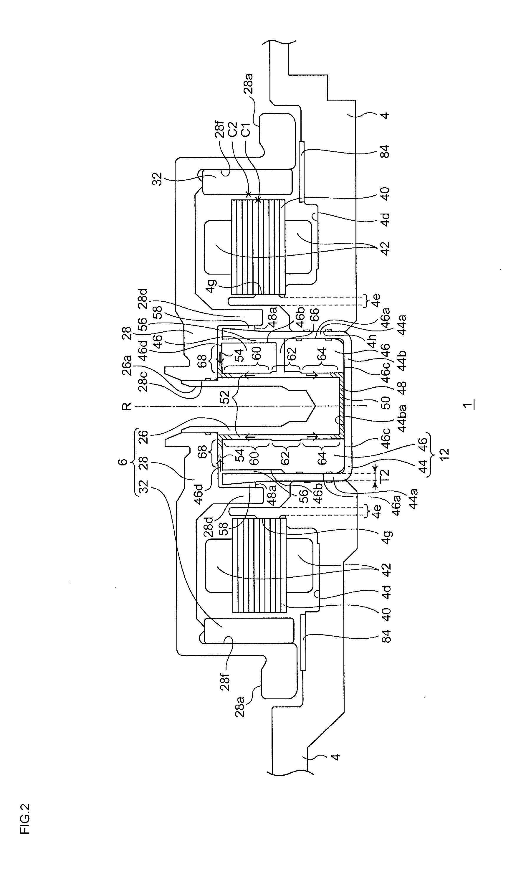
[0027]The magnetic recording disk 8 is a 3.5-inch type glass magnetic recording disk, the diameter of which being 95 mm. The diameter of the central hole of the magnetic recording disk 8 is 25 mm, and the thickness of the disk 8 is 1.27 mm. The magnetic recording disk 8 is mounted on the rotor 6 and rotates therewith. The rotor 6 is rotatably mounted to the base 4 through the bearing unit 12, which is not shown in FIG. 1A.

[0028...

second embodiment

The Second Embodiment

[0067]The first embodiment describes the case where the housing 44 and the sleeve 46 are separately formed. The second embodiment describes the case where the housing and the sleeve are integrated into a single piece of a bearing unit 312.

[0068]FIG. 7 is a section view of a rotating device 301 according to the second embodiment. The rotating device 301 comprises a rotor 306 on which the magnetic recording disk 8 (not shown in FIG. 7) is to be mounted, the bearing unit 312, the base 4, the laminated core 40, the coils 42, and the magnetic ring 84. The rotor 306 includes the shaft 26, a hub 328, the cylindrical magnet 32, and a seal forming unit 382.

[0069]The bearing unit 312 is inserted into the through hole 4h of the base 4 and fixed therein. The bearing unit 312 rotatably supports the rotor 306 with respect to the base 4 via the lubricant 348. The bearing unit 312 is formed to be cup-shaped by integrating a cylindrical portion 344a and a bottom portion 344b as ...


PUM


Abstract

A rotating device comprises a hub, a shaft, and a bearing unit. The bearing unit includes a surrounding portion arranged to surround the shaft, and a facing portion arranged to face an end of the shaft. A gap between the shaft and the surrounding portion includes two dynamic pressure generation portions and an intermediate portion arranged between the two dynamic pressure generation portions. The bearing unit further includes a path of a lubricant arranged to connect one side of one dynamic pressure generation portion and the intermediate portion. The shaft and the bearing unit are arranged so that the lubricant pushed out of the other dynamic pressure generation portion towards a gap between the end of the shaft and the facing portion stays in the gap.

Description

BACKGROUND OF THE INVENTION[0001]1. Field of the Invention[0002]The present invention relates to a rotating device and in particular a rotating device comprising a bearing unit arranged to rotatably support a shaft via a lubricant.[0003]2. Description of the Related Art[0004]Disk drive devices, such as hard disk drives, have become miniaturized. The capacity of a disk drive device has also been increased. Such disk drive devices have been installed in various types of electronic devices. In particular, such disk drive devices have been installed in portable electronic devices such as laptop computers or portable music players.[0005]A fluid dynamic bearing is a known bearing for the disk drive device. Ina fluid dynamic bearing, a lubricant is injected into a gap between a rotor and a stator, and the fluid dynamic bearing maintains a state in which the rotor does not touch the stator by dynamic pressure created in the lubricant when the rotor rotates with respect to the stator (for ex...

Claims


Application Information

Patent Timeline
Patent Type & Authority Applications(United States)
IPC IPC(8): F16C32/06
CPCF16C2240/60F16C2370/12F16C33/745F16C32/0629F16C33/107F16C33/1085F16C17/107
Inventor KONNO, KATSUSHIGENAGAI, KAZUYOSHIGOTO, HIROMITSU
Owner SAMSUNG ELECTRO MECHANICS JAPAN ADVANCED TECHNOLOGY CO LTD
Why Eureka
Try Eureka