Subsea anchor

a technology for anchors and submerged bodies, applied in anchors, vessel construction, borehole/well accessories, etc., can solve the problems of reducing the added mass, disadvantageous affecting the crane assembly, and disadvantageous affecting the top hatch of the prior ar

Active Publication Date: 2013-08-29
AKER SOLUTIONS AS
View PDF2 Cites 32 Cited by
  • Summary
  • Abstract
  • Description
  • Claims
  • Application Information

AI Technical Summary

Benefits of technology

[0008]With such a top aperture and with the top hatch being in an open position, the resistance force from water when lowering or lifting the anchor through water is reduced to below half of the corresponding resistance with a closed top hatch or an anchor without a top hatch. More importantly, the added mass resulting from accelerated water masses when accelerating the anchor is reduced to approximately 10% of the comparable added mass with the top hatch closed. This is a result of the water within the cylindrical body being able to flow almost freely through the open aperture of such relative size. This is particularly advantageous when lowering the anchor through the wave zone with a cable crane on a floating installation, since added mass increases the risk of a slack cable.

Problems solved by technology

In particular, one needs to avoid a slack cable which may disadvantageously affect the crane assembly.
However, such top hatches of the prior art are disadvantageously small and contributes to reduction of the added mass only to a small extent.
However, having a circular top plate with two or three top hatches in it only opens a small part of the total area of the top plate of the anchor.

Method used


Image

  • Subsea anchor
  • Subsea anchor
  • Subsea anchor

Examples


Embodiment Construction

[0015]Whereas some main features of the invention has been described in general terms above, a more detailed non-limiting description of an example of embodiment will be given in the following with reference to the drawings, in which

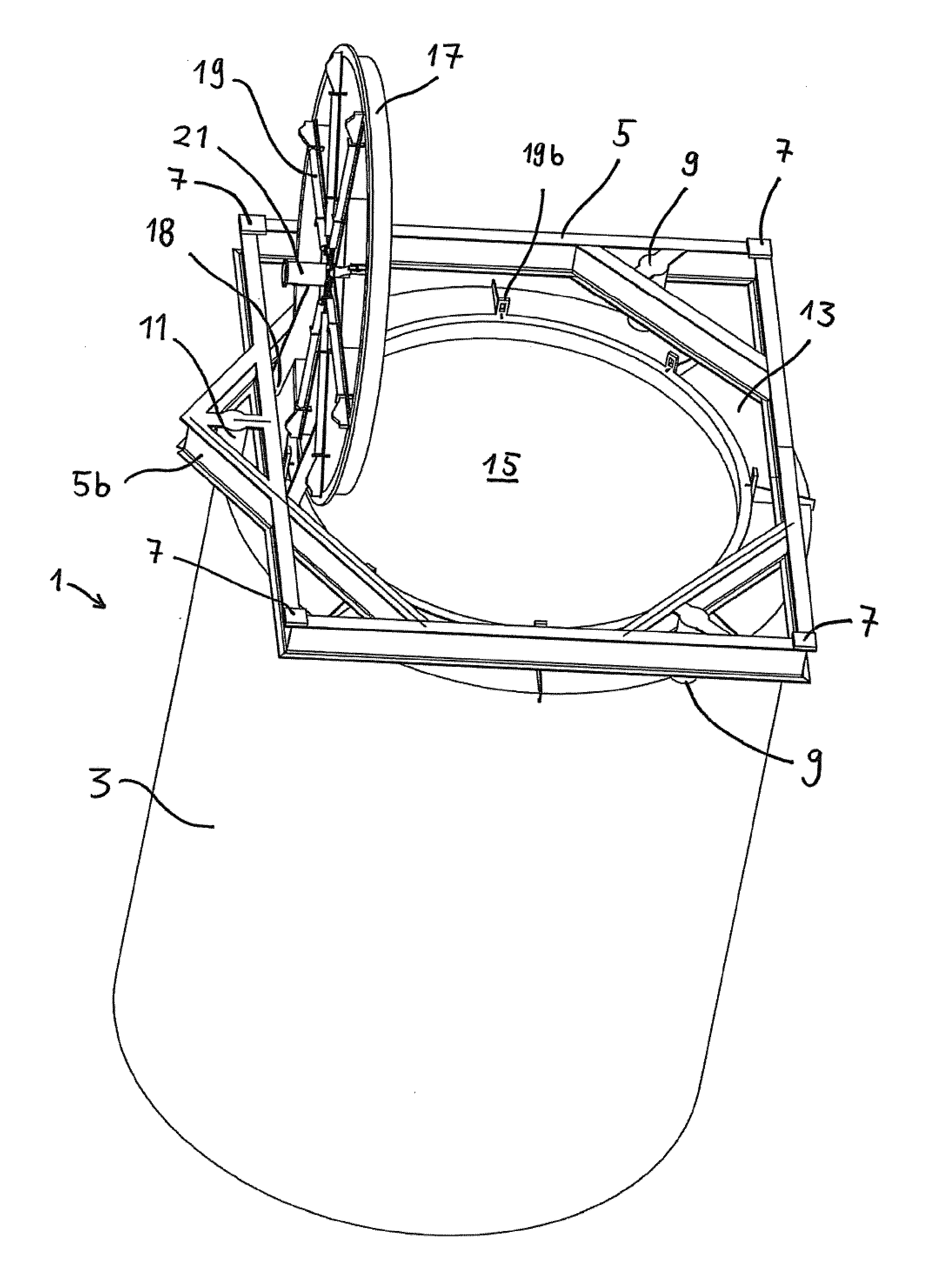
[0016]FIG. 1 is a perspective view of an anchor according to the invention, with a top hatch in an open position;

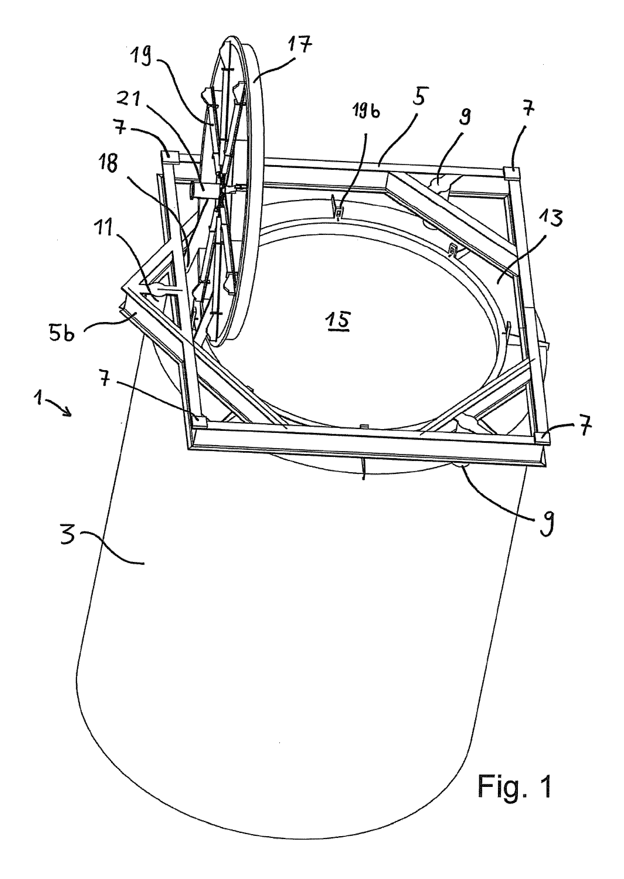
[0017]FIG. 2 is a perspective view of the anchor in FIG. 1, with the top hatch in the closed position;

[0018]FIG. 3 is a top view of the anchor with the top hatch in the closed position;

[0019]FIG. 4 is a side cross section view of the top section of the anchor;

[0020]FIG. 5 is a cross section segment view of the top hatch and a sealing means;

[0021]FIG. 6 is a cross section view of a sealing means between the top hatch and a top plate; and

[0022]FIG. 7 is a perspective view of an alternative embodiment involving an assembly comprising an anchor according to the invention and a well template.

[0023]FIG. 1 shows an anchor 1 according to the present i...


PUM


Abstract

Subsea anchor (1) having a hollow cylindrical body (3) extending down from a top part (13). The anchor has a top aperture (15) and a top hatch (17) which is adapted to close and open the top aperture (15). The cylindrical body (3) is adapted to penetrate into a seabed. The area of said aperture (15) is at least 30% of the corresponding cross section area encircled by the cylindrical body (3).

Description

[0001]The present invention relates to a subsea anchor for anchoring subsea equipment to the seabed.BACKGROUND[0002]For anchoring floating installations or subsea equipment to the sea floor, it is known to penetrate the seabed with cylinder shaped skirts. Some of these are known as suction anchors, which are arranged to penetrate the seabed by providing a lower pressure inside the cylinder than on the outside. Others are simply forced into the seabed by gravity. These anchors rely on friction forces between the cylindrical shaped skirt and the seabed.[0003]Patent publication U.S. Pat. No. 6,910,831 describes an anchor which is arranged to penetrate into the seabed by providing a negative pressure inside of it.[0004]In order to provide such a negative pressure the cylindrical shape of the anchor must be closed at the top section. Thus, the main shape of the anchor is the cylindrical side wall and a top plate. Furthermore, it is known to arrange a hatch in the top plate. By opening th...

Claims


Application Information

Patent Timeline
Patent Type & Authority Applications(United States)
IPC IPC(8): B63B21/27
CPCE21B41/08B63B21/27
Inventor MOGEDAL, KNUTKRISTIANSEN, BARD
Owner AKER SOLUTIONS AS
Why Eureka
Try Eureka