

Trolley brake and method of using same
a technology of roller brake and roller, which is applied in the direction of railway components, mechanical equipment, transportation and packaging, etc., can solve the problems of no braking system presently available, no braking system for the rider, and the downward slope of the suspended cabl
- Summary
- Abstract
- Description
- Claims
- Application Information
AI Technical Summary
Benefits of technology
Problems solved by technology
Method used
Image

Examples
Embodiment Construction
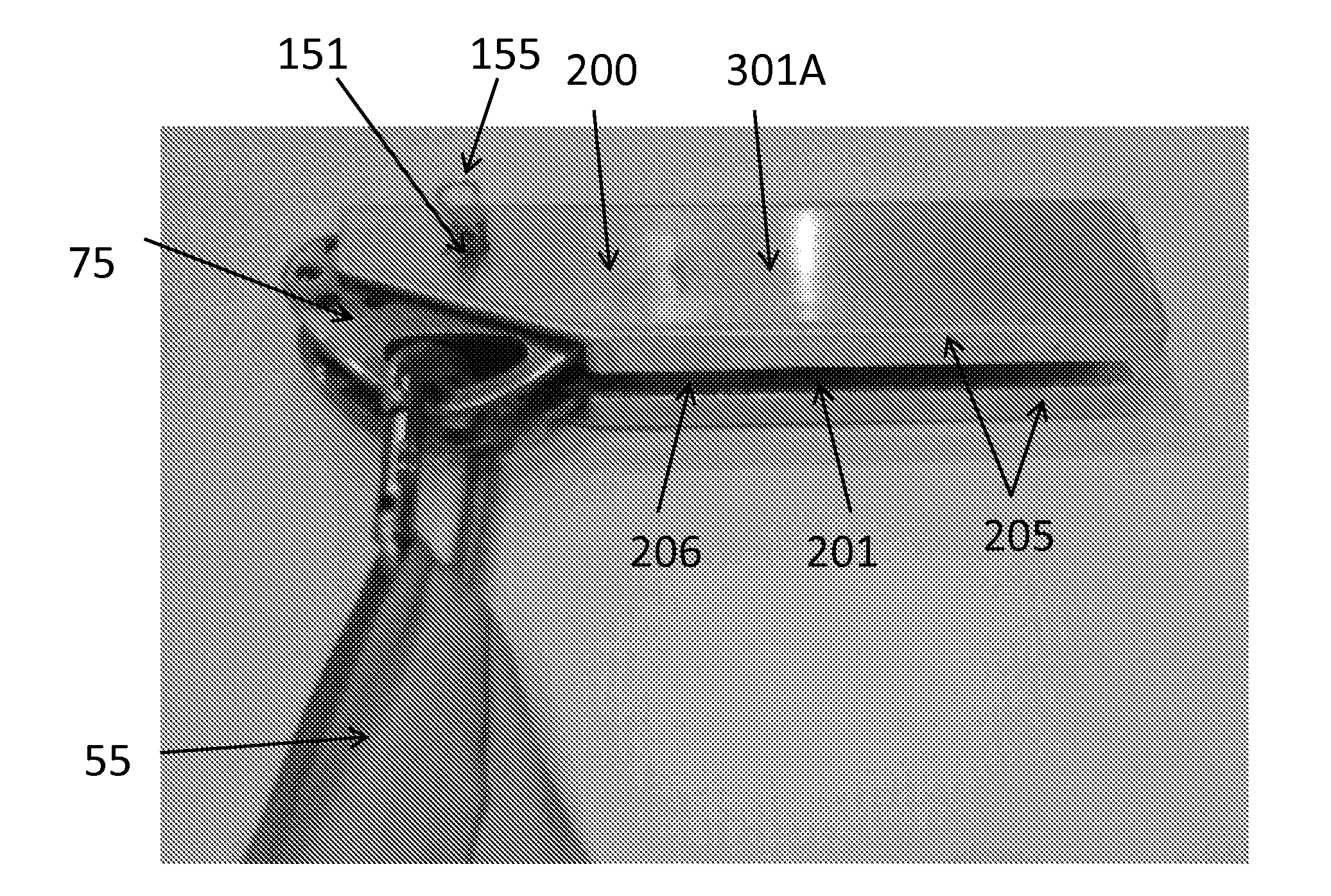
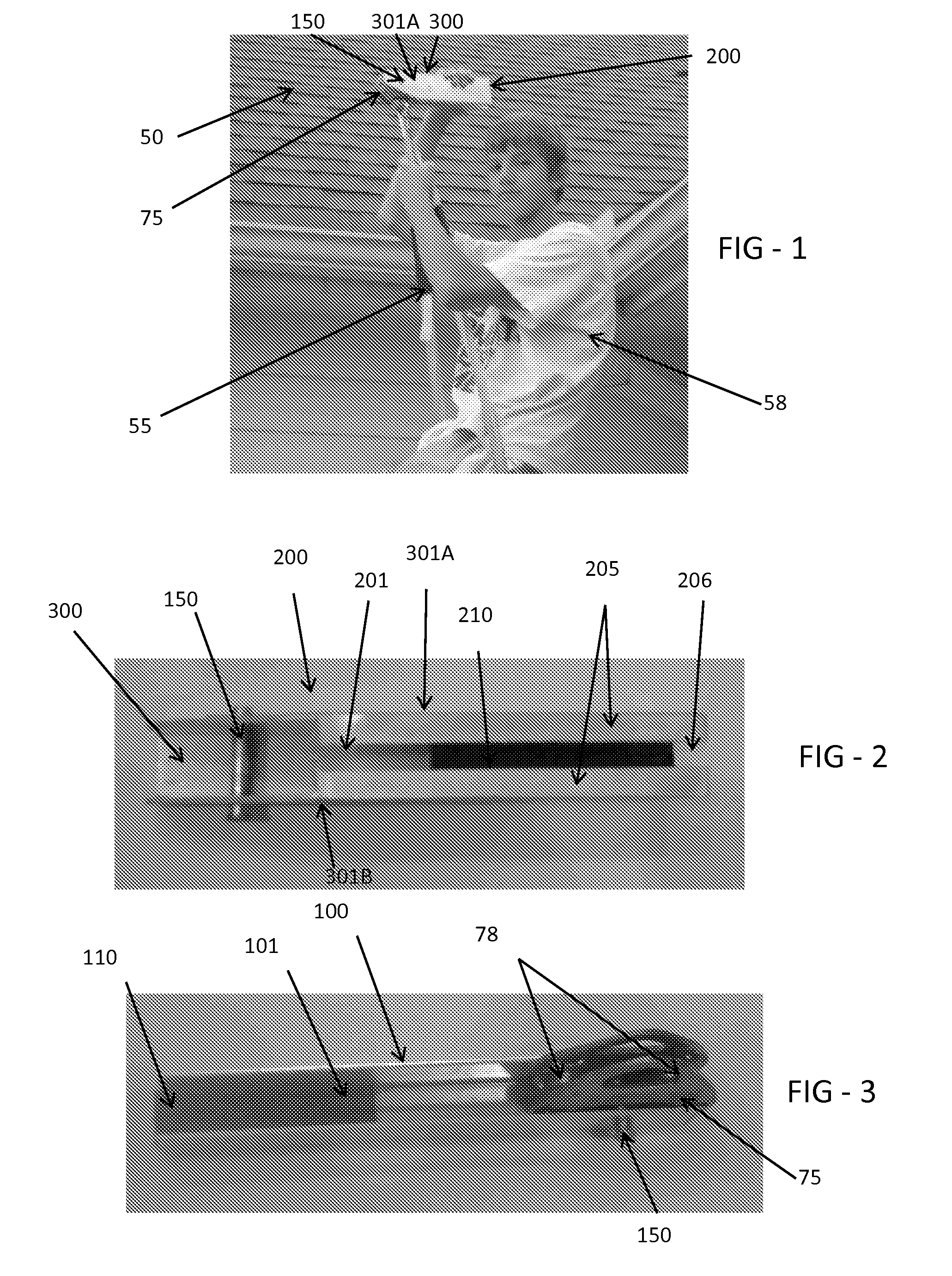
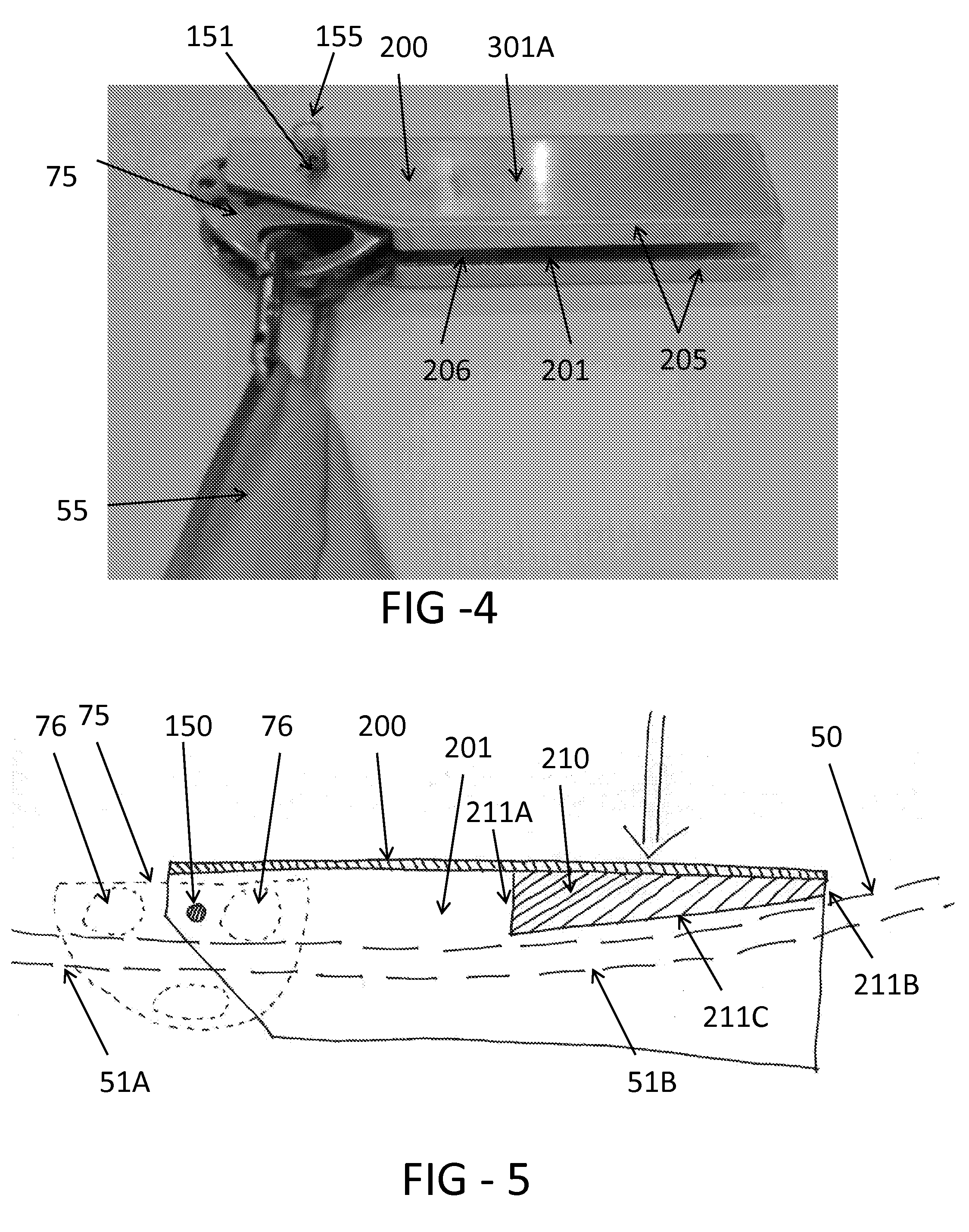
[0011]Exemplary embodiments relate to a trolley brake having a brake body which is fastened to the trolley. The zip line preferably travels below a pair of rollers or pulleys on the trolley and through a center channel of the brake body. A brake pad may be placed between the zip line and a bottom portion of the brake body such that a downward force on the brake body causes the brake pad to contact the zip line. More downward force applies more braking force to the zip line and vice versa so that the user can precisely control the desired amount of braking. The brake pad may be oriented with an upward angle as you move from the trolley to the rear of the brake body to account for a natural arc created in the zip line when loaded with the weight of a user.
[0012]The foregoing and other features and advantages will be apparent from the following more detailed description of the particular embodiments of the invention, as illustrated in the accompanying drawings.
BRIEF DESCRIPTION OF THE ...
PUM
 Abstract
Description
Claims
Application Information