Trenchless Pipe Replacement of Underground Pipe

a technology for underground pipes and trenchless removal, which is applied in the direction of electrical equipment, cables, electrical cable installations, etc., can solve the problems of inability to easily re-excavate, unacceptably costly re-excavation, and difficult replacement of underground pipes, and achieve the effect of double speed

Active Publication Date: 2013-08-29
SOL JONATHAN +1
View PDF5 Cites 4 Cited by
  • Summary
  • Abstract
  • Description
  • Claims
  • Application Information

AI Technical Summary

Benefits of technology

[0009]The present invention comprises an improved cable puller for the trenchless replacement of underground pipes including water, sewer, and electrical conduits. The cable puller of the present invention improves upon prior art hydraulic cable pullers. Unlike the single-acting pullers of the prior art which pull only on their outward stroke and do little, or no, useful work on their inward or recovery stoke, the present invention cable puller pulls continuously on the cable on both the device's outward and inward strokes and therefore doubles the speed at which a mole may be pulled through a pipe to be burst. Moreover, because the device pulls the cable on both its inward and outward strokes, the present invention puller has no need for a mechanism to hold the cable stationary during the return stroke as is required by the prior art. Such a device however, may be provided with the present invention puller for added safety.

Problems solved by technology

The underground location of water and sewer lines, as well as electrical conduits, makes their replacement difficult.
Often such lines were installed via open trenches years ago and now they cannot be easily re-excavated.
Over the years, new developments, such as roads, parking lots, buildings, or landscaping have been placed over the surface of the old lines, thus making re-excavation impossible or unacceptably costly.
However, winches of sufficient size to generate 75 tons of pulling force typically weigh several tons themselves and are frequently mounted on trucks or are attached to other large excavation devices.
In some applications, space limitations prevent the use of a winch as the source of pulling force.
The pulling device of the Carter patent however, nevertheless suffers from certain drawbacks.
One drawback of the Carter device is that because the device uses single acting hydraulic cylinders, it has a relatively slow cycle time.
Another drawback of the Carter device is that to prevent the cable from rebounding back into the pipe to be burst, the device requires additional hardware to hold the pulling cable stationary while the hydraulic cylinders make their return stroke.

Method used


Image

  • Trenchless Pipe Replacement of Underground Pipe
  • Trenchless Pipe Replacement of Underground Pipe
  • Trenchless Pipe Replacement of Underground Pipe

Examples


Embodiment Construction

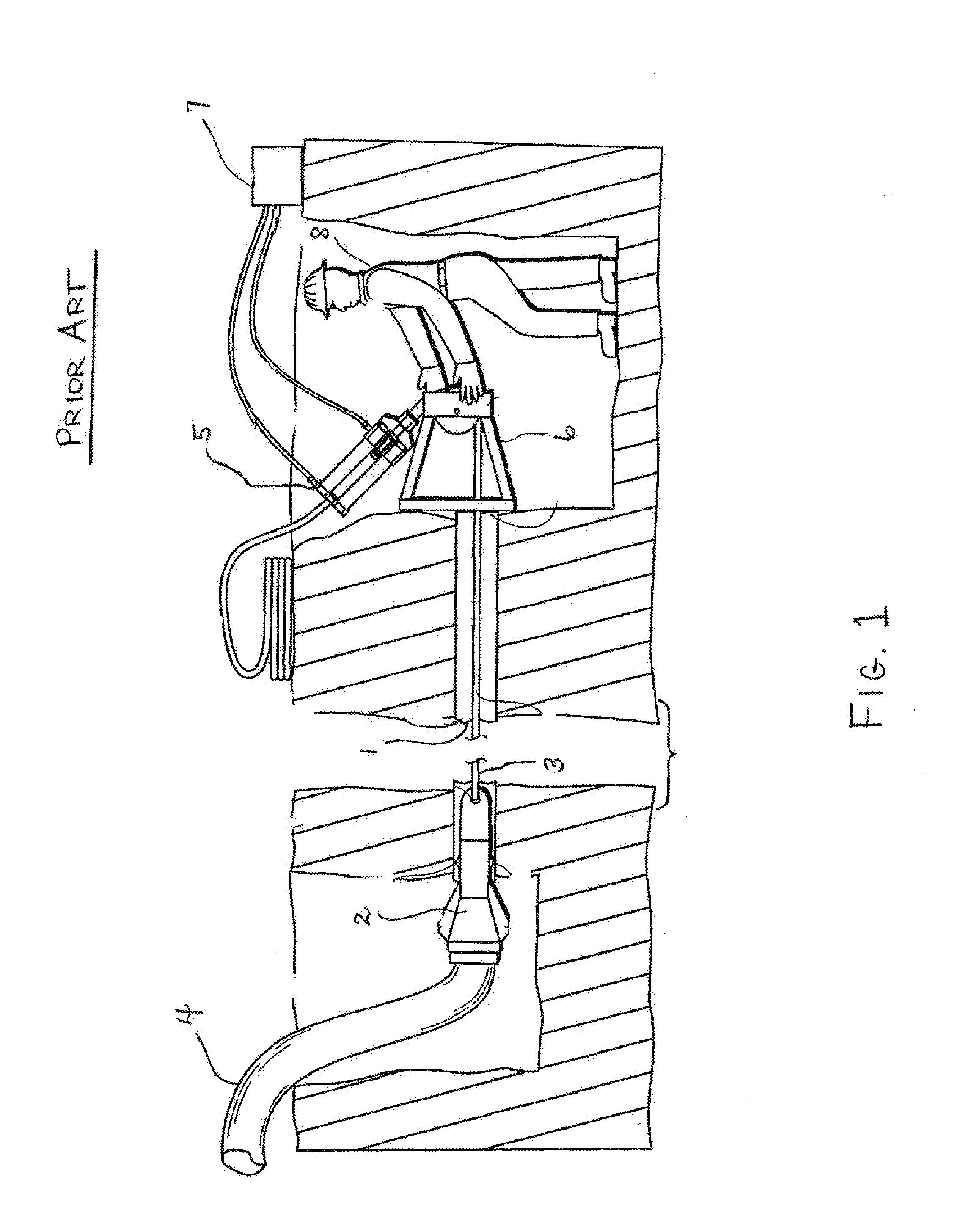
[0022]With reference to FIG. 1, it has long been known in the art that an old pipe 1, i.e. water, sewer, or electrical conduit, can be replaced by pulling a mole 2 via a cable 3 through the pipe to be burst 1, and thereby bursting the pipe in a radially outward direction. Typically, a length of flexible plastic pipe 4 is drawn through the burst pipe 1 and thereby takes the place of the burst pipe 1. Prior art systems require a means for generating the pulling force on the cable 1 and this means has typically been supplied by winches (not shown) or by a hydraulic cylinder-based cable puller 5. Hydraulic cylinder-based cable pulling systems further require a pulling frame 6 that faces an opening in the pipe to be burst 1 through which the cable 3 may be drawn. Such systems further require a source of pressurized hydraulic fluid 7 and at least one operator 8. As noted in the background section, prior art systems pull the cable only on their outward stroke.

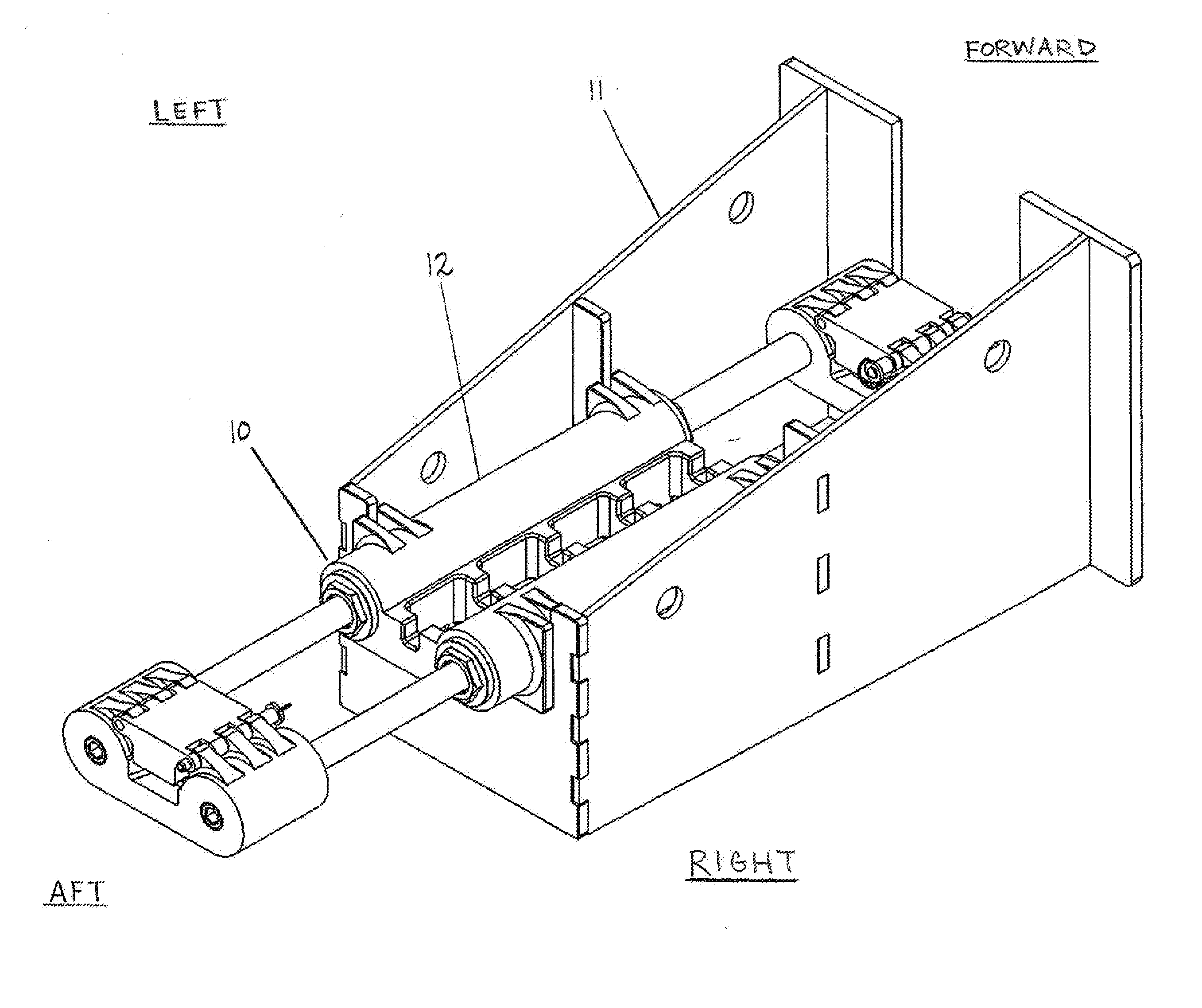
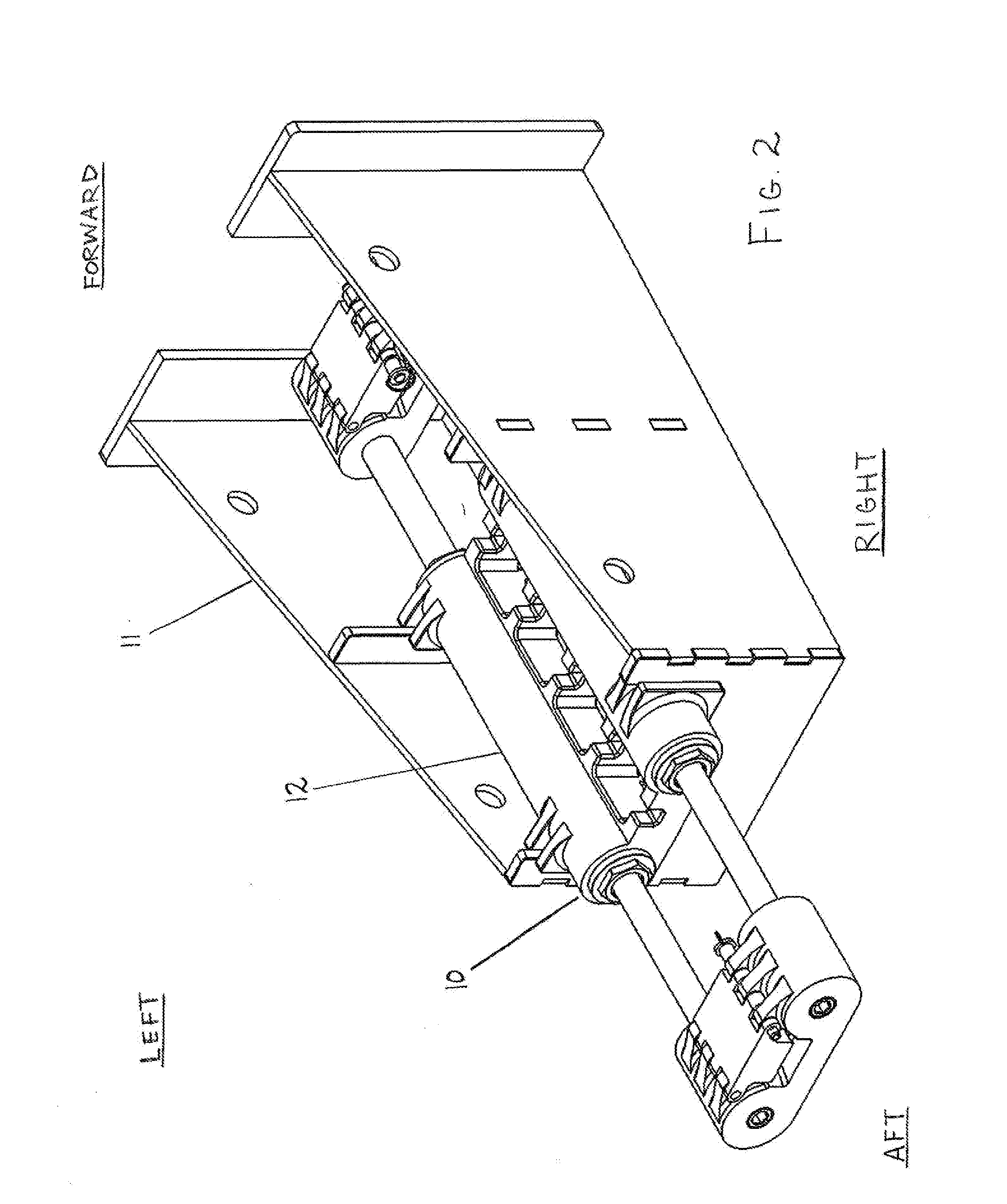
[0023]Referring to FIG. 2, the...


PUM


Abstract

The present invention comprises an improved cable puller assembly for use in the trenchless replacement of underground pipes including water, sewer and electrical conduits. The improved cable puller assembly utilizes a cylinder body comprising four double acting hydraulic cylinders set up in pairs of two, i.e. two forward cylinders and two aft cylinders. The cable pullers are configured to move inwardly and outwardly from the cylinder body and feature the ability to pull a cable through a pipe on both their inward and outward strokes.

Description

FIELD OF THE INVENTION[0001]The invention relates generally to systems for use in the trenchless removal of underground pipe, and more particularly, to systems which use hydraulic cylinders as the cable puling device.BACKGROUND OF THE INVENTION[0002]The underground location of water and sewer lines, as well as electrical conduits, makes their replacement difficult. This is particularly so where additional infrastructure has been developed around or on the previously built underground lines or conduits. Often such lines were installed via open trenches years ago and now they cannot be easily re-excavated. Over the years, new developments, such as roads, parking lots, buildings, or landscaping have been placed over the surface of the old lines, thus making re-excavation impossible or unacceptably costly.[0003]Numerous methods have been developed over the years to address the problem of how to replace worn out water and sewer lines without excavating the lines. Typically, such methods ...

Claims


Application Information

Patent Timeline
Patent Type & Authority Applications(United States)
IPC IPC(8): H02G1/08
CPCH02G1/081
Inventor SOL, JONATHANSOL, ROELOF
Owner SOL JONATHAN
Why Eureka
Try Eureka