Imaging apparatus

a technology an irradiation chamber, which is applied in the field of irradiation chambers, can solve problems such as the upsizing of a drive uni

Active Publication Date: 2013-08-29
FUJIFILM CORP
View PDF0 Cites 67 Cited by
  • Summary
  • Abstract
  • Description
  • Claims
  • Application Information

AI Technical Summary

Benefits of technology

[0056]According to the present invention, it becomes possible to select an image with a desired focal length. Since pixels can be selected and synthesized according to an object distance in particular, a wide range of object distances can be suppor

Problems solved by technology

If the focus adjustment mechanism is incorporated in the imaging lens in order to ta

Method used


Image

  • Imaging apparatus
  • Imaging apparatus
  • Imaging apparatus

Examples


Embodiment Construction

[0094]While the present invention is to be described hereinafter through embodiments of the invention, it should be understood that the following embodiments do not limit the invention defined by the claims. It should also be understood that not all the combinations of the characteristics described in the embodiments are necessarily indispensable as the solution of the invention.

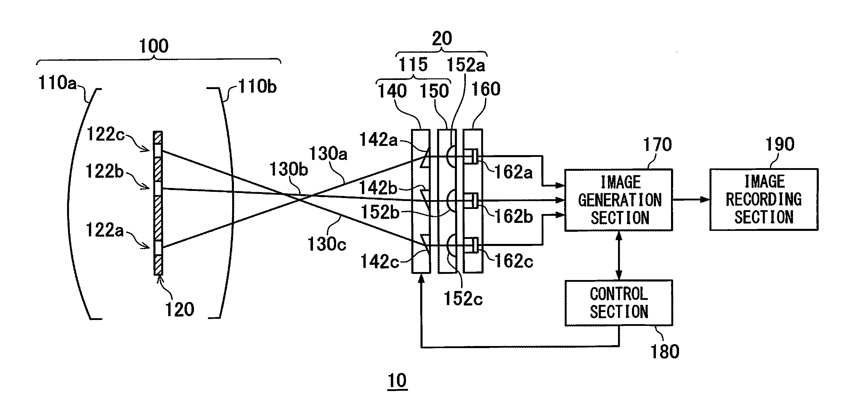
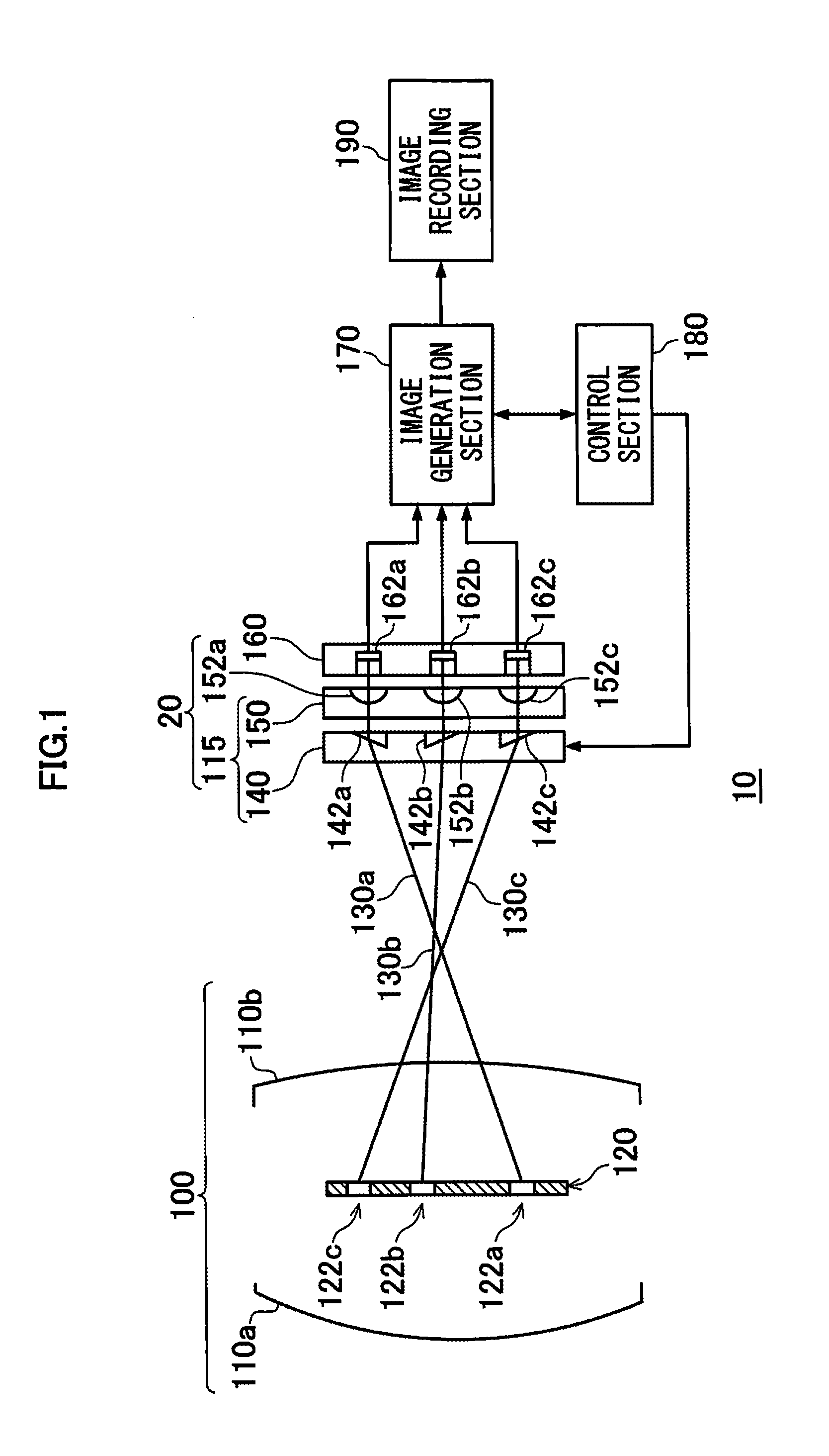
[0095]FIG. 1 schematically shows one example of a block configuration of an imaging apparatus 10. The imaging apparatus 10 according to the present embodiment provides a function to take images with different focal lengths. In particular, an optical configuration of the imaging apparatus 10 provides an imaging apparatus capable of compactly mounting the function with use of a fixed imaging lens. The imaging apparatus 10 includes a lens system 100, a light receiving unit 20, an image generation section 170, a control section 180, and an image recording section 190. The light receiving unit 20 has an optical d...


PUM


Abstract

An imaging apparatus, including: an image formation lens having focal lengths different in every region; a light receiving section having light receiving elements; optical elements corresponding to a plurality of the light receiving elements to make the corresponding light receiving elements receive an object light beam that passed through predetermined pupil regions in an exit pupil of the image formation lens; and an image generation section, wherein in the case of selecting, for generation of the image of the object, any one of the pupil regions in the exit pupil through which an object light beam passes, the image generation section selects, based on an object distance and focal lengths each corresponding to a plurality of the pupil regions of the exit pupil, at least one of the pupil regions through which an object light beam that forms an image at a position of the light receiving section passes.

Description

CROSS-REFERENCE TO RELATED APPLICATIONS[0001]This application is a continuation application and claims the priority benefit under 35 U.S.C. §120 of PCT Application No. PCT / JP2011 / 070796 filed on Sep. 13, 2011 which application designates the U.S., and also claims the priority benefit under 35 U.S.C. §119 of Japanese Patent Applications No. 2010-224234 filed on Oct. 1, 2010, No. 2011-116180 filed on May 24, 2011, and No. 2011-176229 filed on Aug. 11, 2011, which applications are all hereby incorporated by reference in their entireties.TECHNICAL FIELD[0002]The present invention relates to an imaging apparatus and more particularly relates to a technology for simultaneously acquiring images with different focal lengths.BACKGROUND ART[0003]Regarding an optical element provided in the vicinity of an image sensor, there are known, for example, technologies disclosed in PTL 1 and PTL 2.[0004]PTL 1 discloses a parallax image input apparatus adapted to selectively image information that pass...

Claims


Application Information

Patent Timeline
IPC IPC(8): H04N5/232
CPCG02B3/14G03B13/32G03B17/02H04N5/23296H04N5/2259H04N5/23212H04N5/23229H04N5/2254H04N23/957H04N23/58H04N23/67H04N23/672H04N23/80H04N23/69
Inventor ONO, SHUJI
Owner FUJIFILM CORP
Why Eureka
Try Eureka