360° imaging system

Active Publication Date: 2013-08-29
OVIO TECH INC
View PDF7 Cites 31 Cited by
  • Summary
  • Abstract
  • Description
  • Claims
  • Application Information

AI Technical Summary

Benefits of technology

[0005]The “camera” end of the horizontal boom has a vertical arm or boom that extends downwardly and has the camera mounted thereon. The vertical arm or boom can be telescopic allowing lengthening or shortening to adjust the camera height. The “backdrop” end of the horizontal boom also includes a vertical arm or boom. This vertical arm or boom has the backdrop mounted thereon and travels opposite the video camera as the horizontal boom rotates. A lighting system is mounted on the “camera” end of the horizontal boom and on the vertical arm or boom that holds the imaging device. The lighting system provides downward lighting and front lighting of th

Problems solved by technology

However, often a photograph from one angle or even several

Method used


Image

  • 360° imaging system
  • 360° imaging system
  • 360° imaging system

Examples


Embodiment Construction

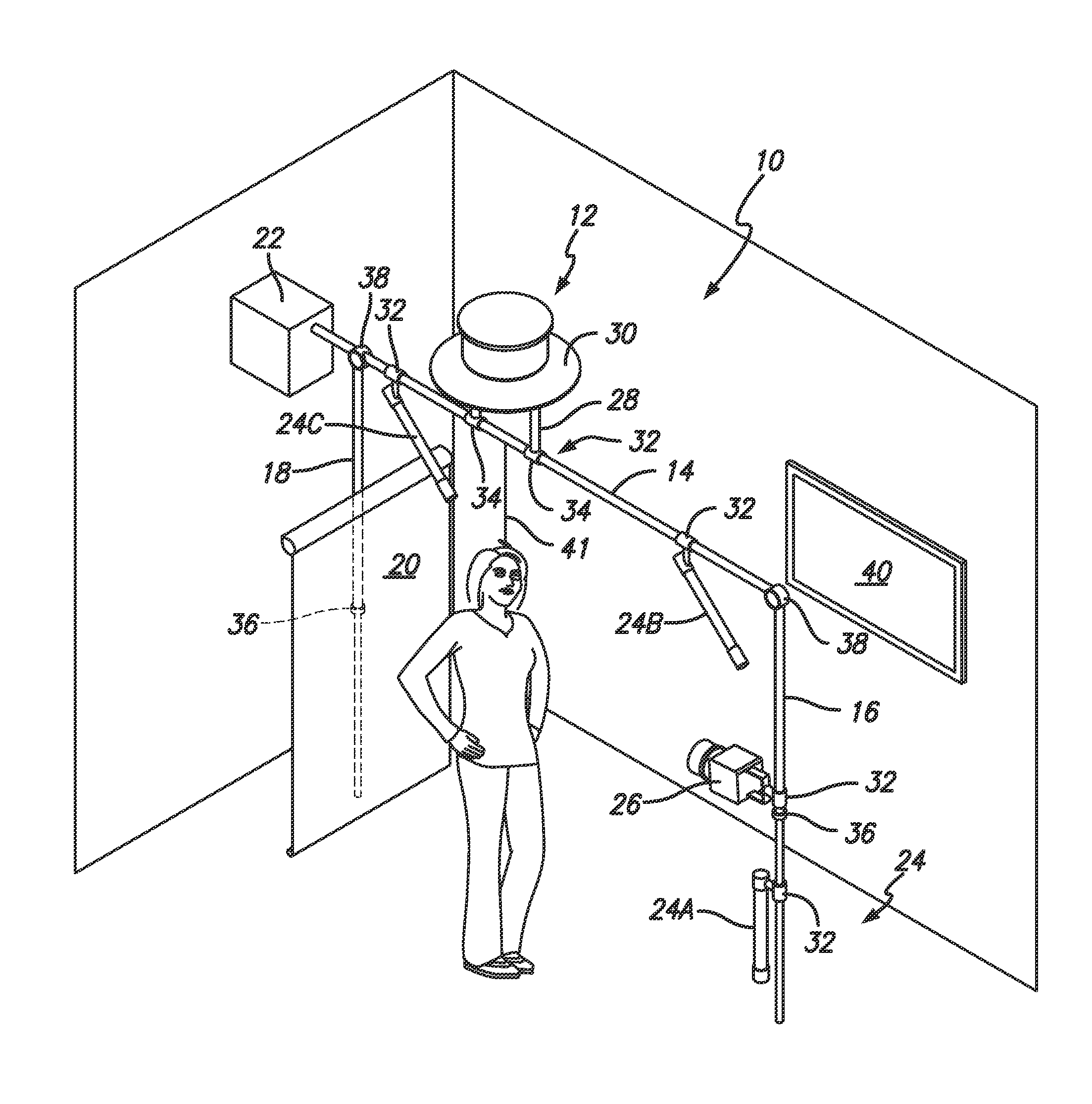
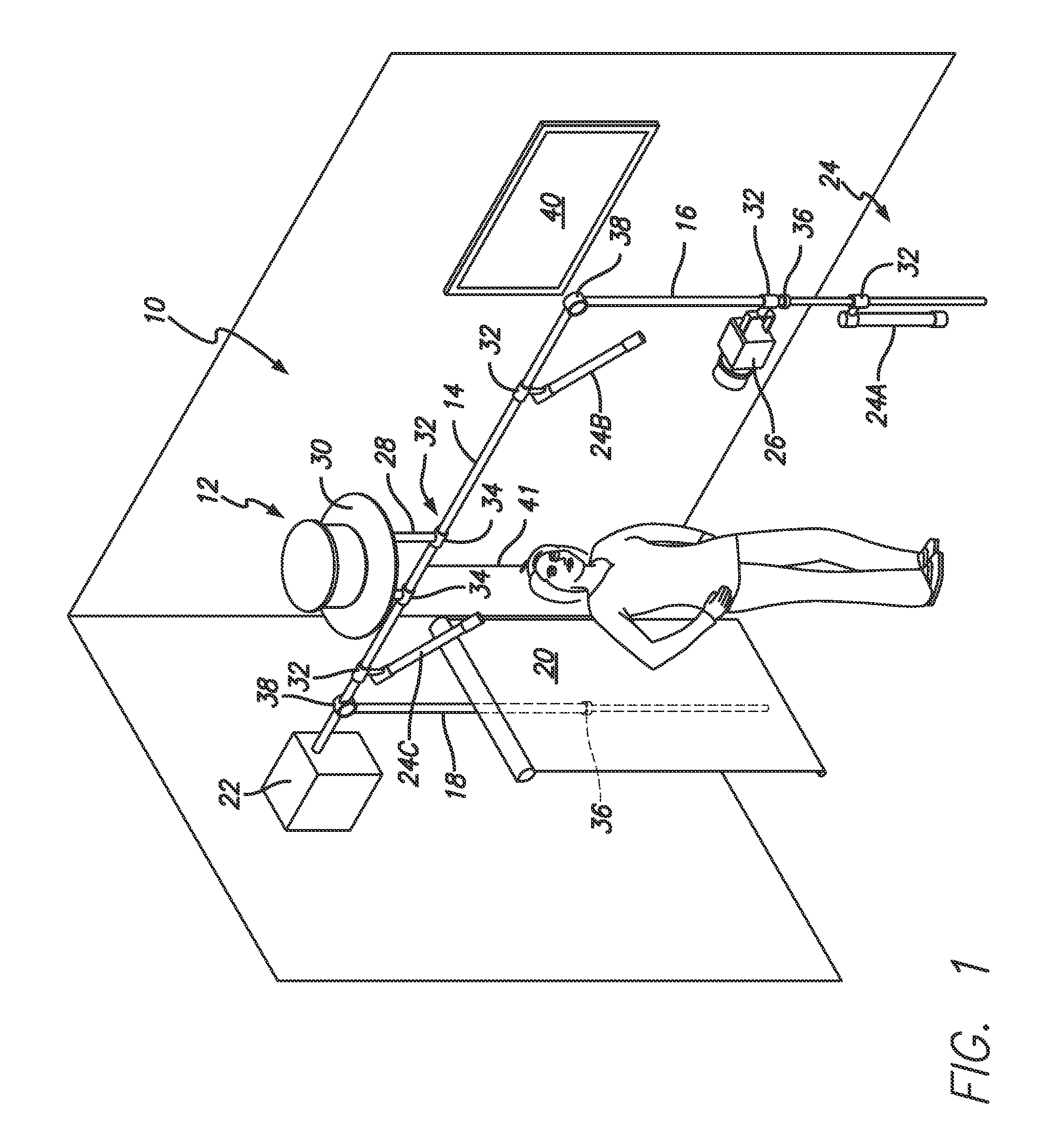
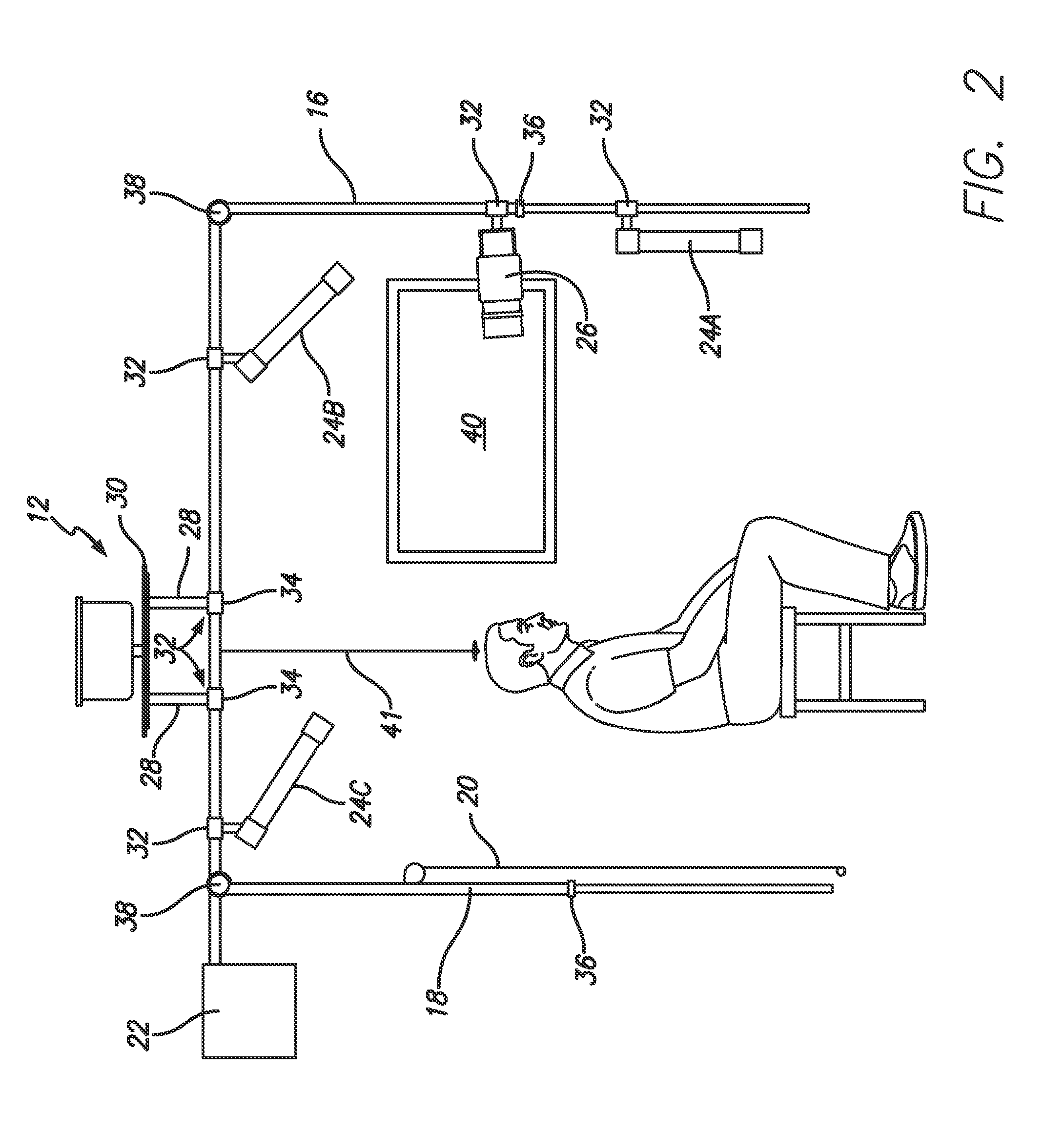
[0004]The invention includes an articulated swiveling horizontal boom adapted to carry on one of its extremities a device, such as a video camera, still camera or other imaging device, which can be moved 360°. On the opposite end of the horizontal boom is mounted a backdrop that will rotate in synchrony about the vertical axis with the camera. The horizontal boom swivels about a vertical axis with the camera at one end and the background attached to the opposite end. The subject to be filmed is placed in a position that is generally co-axial with the vertical axis and is fixed in position. The camera travels 360° around the subject obtaining video imaging of the subject.

[0005]The “camera” end of the horizontal boom has a vertical arm or boom that extends downwardly and has the camera mounted thereon. The vertical arm or boom can be telescopic allowing lengthening or shortening to adjust the camera height. The “backdrop” end of the horizontal boom also includes a vertical arm or boom...


PUM


Abstract

A 360 degree camera imaging system comprising a first horizontal boom having a first end, a second end, and a middle section; a second horizontal boom having a first end and a second end; a first vertical arm having a first end and a second end; a second vertical arm having a first end and a second end; and a mounting bracket. The first horizontal boom is connected to the first end of the second horizontal boom by a first rotatable pivot proximate the middle section of the first horizontal boom, and the second end of the second horizontal boom is connected to the mounting bracket. The first end of the first vertical arm is affixed to the first end of the first horizontal boom, and the first end of the second vertical arm is affixed to the second end of the first horizontal boom. A camera is mounted to the first vertical arm, and a backdrop is mounted to the second vertical arm.

Description

CROSS REFERENCE TO RELATED APPLICATIONS[0001]This application claims the benefit of U.S. Provisional Patent Application No. 61 / 603,853, filed on Feb. 27, 2012, and U.S. Provisional Patent Application No. 61 / 667,108, filed on Jul. 2, 2012, the entireties of which are incorporated herein by reference.FIELD OF THE INVENTION[0002]The present invention relates to a 360° imaging system, and more particularly to a 360° imaging system that can be used to image a patient prior to plastic surgery.BACKGROUND OF THE INVENTION[0003]In the field of plastic surgery, it is often desirable to document a patient's appearance before and after surgery. Photography is the usual means of documentation. However, often a photograph from one angle or even several angles is not sufficient to show the true transformation. Accordingly, a need exists for a system that documents up to a full 360° view of a patient before and after surgery.SUMMARY OF THE PREFERRED EMBODIMENTS[0004]The invention includes an articu...

Claims


Application Information

Patent Timeline
IPC IPC(8): G03B17/56
CPCF16M11/18F16M13/027G03B17/561A61B5/6889A61B5/0064A61B5/0077A61B5/1079F16M11/046F16M11/048F16M11/2014F16M11/2021F16M11/28F16M11/42F16M13/02G03B15/06G03B37/02G03B15/00H04N23/00
Inventor MUELLER, GREGORY PAULGAGLIANO, TEDKREUSER, CHARLESSALTER, KENNETH D.
Owner OVIO TECH INC
Why Eureka
Try Eureka