Method for reducing intermodulation noise signal and communication terminal

a technology of intermodulation noise and communication terminal, which is applied in the direction of power management, electrical equipment, echo effect reduction, etc., can solve the problems of reducing the strength of the lte transmitting signal, affecting data communication, and affecting the quality of communication, so as to reduce the intermodulation noise signal

Inactive Publication Date: 2013-08-29
PANTECH CO LTD
View PDF6 Cites 17 Cited by
  • Summary
  • Abstract
  • Description
  • Claims
  • Application Information

AI Technical Summary

Benefits of technology

[0012]Exemplary embodiments of the present invention provide a method for reducing an intermodulation noise signal.

Problems solved by technology

In this instance, intermodulation noise of a voice channel, and the like, may be generated and a communication quality may be degraded.
However, in the related technology, although a level of noise caused by an intermodulation signal may be changed since a level of the LTE transmitting signal to be received by a CDMA 1X receiving end keeps changing in real time, depending on a peripheral environment and / or a manner of grapping a communication terminal, the strength of the LTE transmitting signal may be decreased based on only the strength of the CDMA 1X transmitting signal.
Accordingly, there may be unnecessary restrictions on data communication.
Conversely, if the SNR is relatively low, and the communication quality is poor although the strength of the CDMA 1X transmitting signal is relatively small, the strength of the LTE data transmitting signal may need to be lowered to prevent a call from being dropped.

Method used


Image

  • Method for reducing intermodulation noise signal and communication terminal
  • Method for reducing intermodulation noise signal and communication terminal
  • Method for reducing intermodulation noise signal and communication terminal

Examples


Embodiment Construction

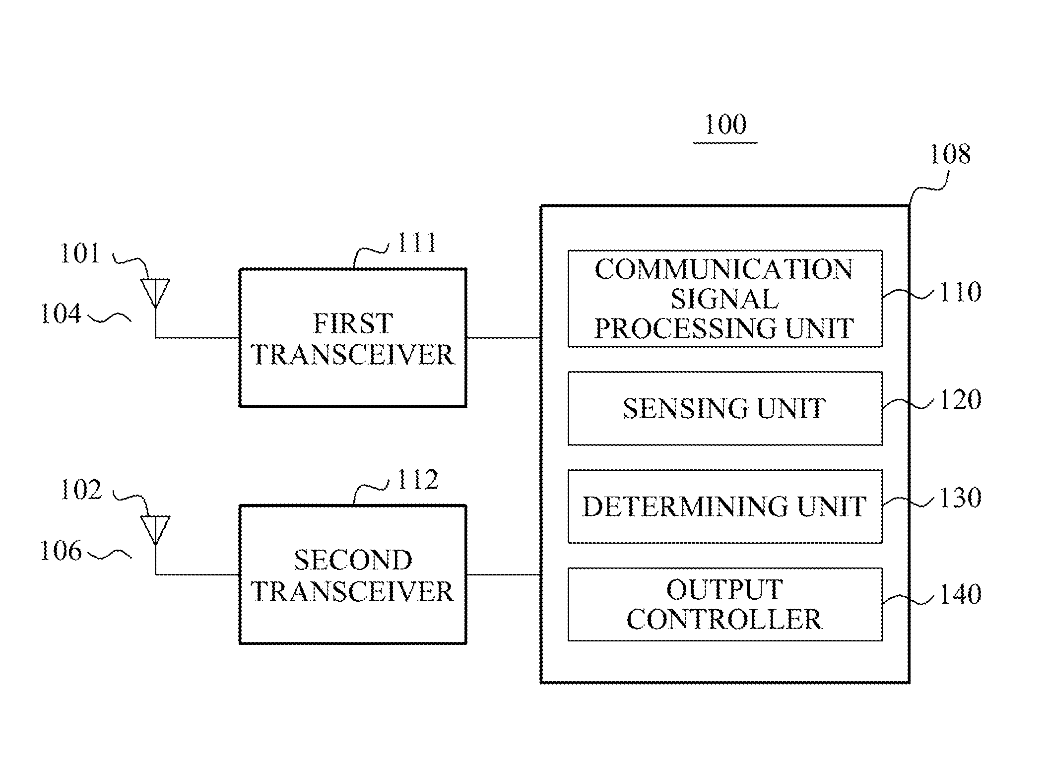
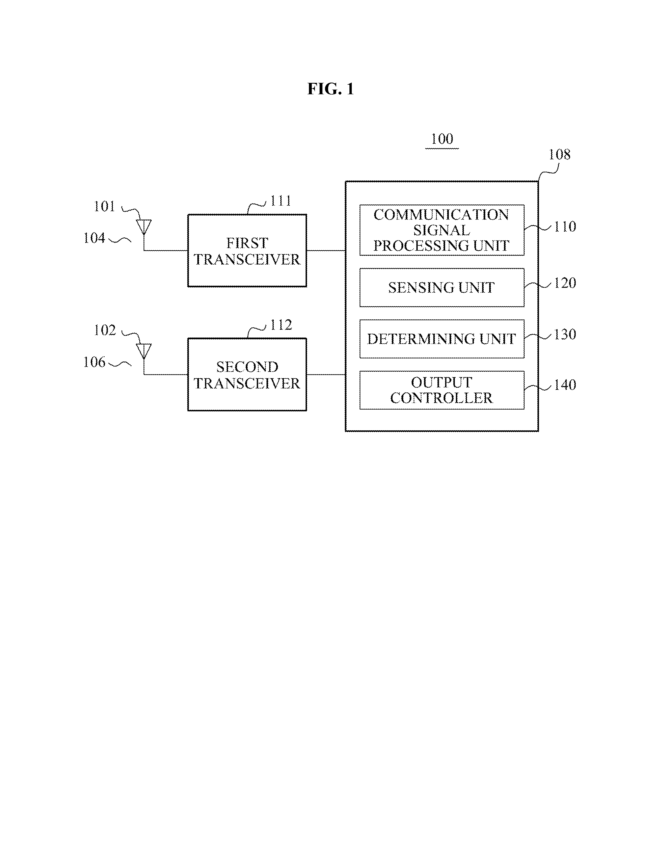
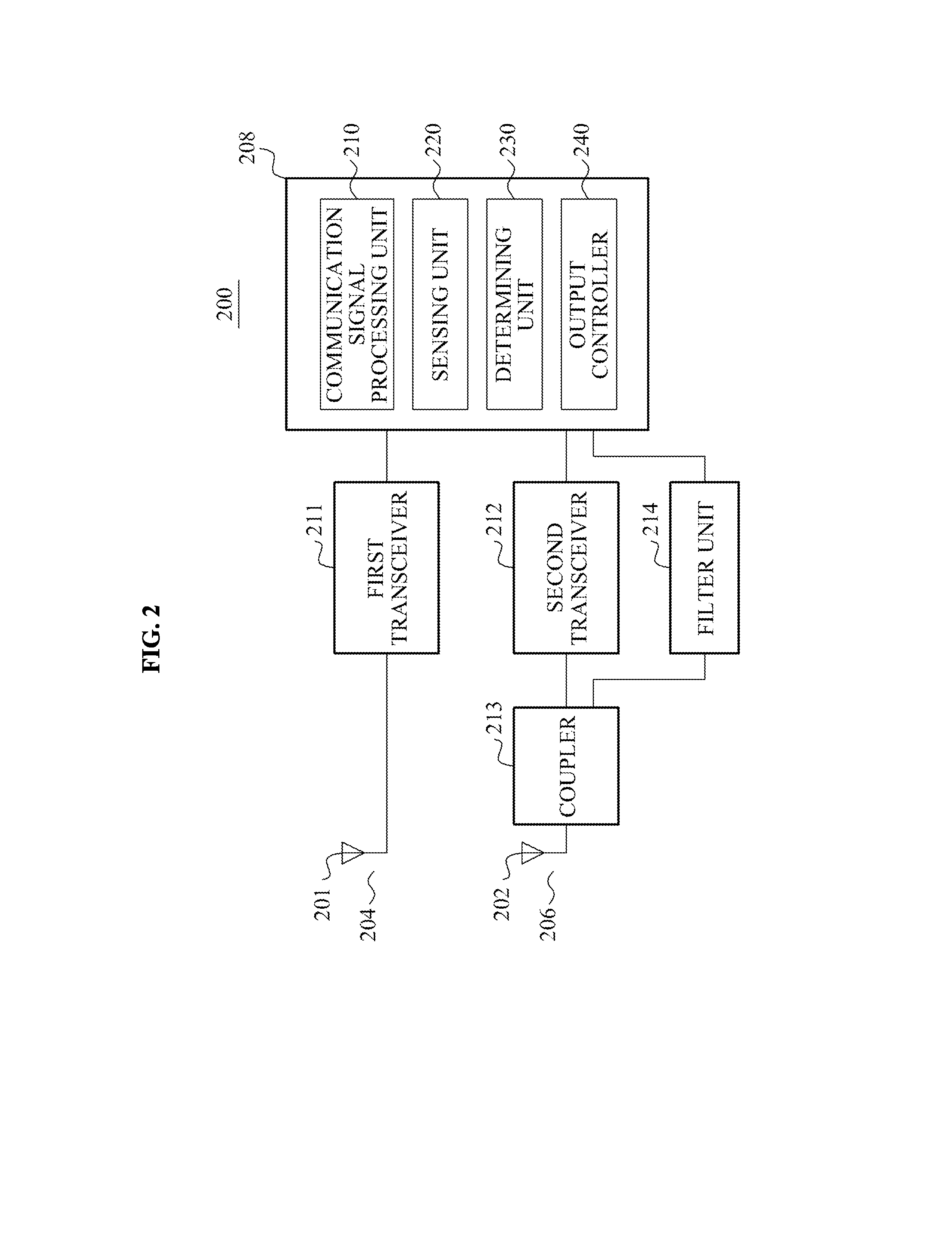
[0029]The invention is described more fully hereinafter with reference to the accompanying drawings, in which exemplary embodiments of the invention are shown. This invention may, however, be embodied in many different forms and should not be construed as limited to the exemplary embodiments set forth herein. Rather, these exemplary embodiments are provided so that this disclosure is thorough, and will fully convey the scope of the invention to those skilled in the art. In the drawings, the size and relative sizes of layers and regions may be exaggerated for clarity. Like reference numerals in the drawings denote like elements. Although features may be shown as separate, such features may be implemented together or individually. Further, although features may be illustrated in association with an exemplary embodiment, features for one or more exemplary embodiments may be combinable with features from one or more other exemplary embodiments.

[0030]It will be understood that when an el...


PUM


Abstract

A communication terminal apparatus to reduce an intermodulation noise between channels may perform wireless communication at different frequencies using a first channel and a second channel. The communication terminal apparatus may include a sensing unit to measure a signal to noise ratio (SNR) in a communication associated with the second channel, a determining unit to determine whether the measured SNR is less than a first threshold, and an output controller to decrease a strength of an output signal in the communication associated with the first channel if the measured SNR is less than the first threshold, and to increase the strength of the output signal in the communication associated with the first channel until the SNR is substantially similar to the first threshold if the determining unit determines that the measured SNR is greater than the first threshold.

Description

CROSS-REFERENCE TO RELATED APPLICATION[0001]This application claims priority from and the benefit of Korean Patent Application No. 10-2012-0021385, filed on Feb. 29, 2012, which is hereby incorporated by reference for all purposes as if fully set forth herein.BACKGROUND[0002]1. Field[0003]The following description relates to a method for reducing a noise signal generated if a transmitting signal of an antenna is received by another antenna.[0004]2. Discussion of the Background[0005]Wireless data transmission using a communication terminal may be generalized and communication terminals may include a plurality of antennas to transmit signals of different frequencies, often simultaneously.[0006]However, among the plurality of antennas, if a signal transmitted by an antenna A is received by an antenna B, the signal transmitted by antenna A may act as a noise signal in antenna B. If the signal transmitted by the antenna A is combined with a transmitting signal of the antenna B and interm...

Claims


Application Information

Patent Timeline
Patent Type & Authority Applications(United States)
IPC IPC(8): H04B15/00
CPCH04B15/00H04W52/16H04W52/226H04W52/241H04W52/243H04B7/015H04W88/06
Inventor HONG, SEOK JINSONG, YONG CHUN
Owner PANTECH CO LTD
Why Eureka
Try Eureka