[0020]Advantageously, forming the channel structure in a transparent material facilitates optical analysis, e.g. any device incorporating the channel structure can be placed over a
light source for viewing of processes that take place within the device. An additional
advantage of the present invention is that rounded channel inlets can be formed. In the context of
patch clamp applications, for example, circular geometries are known to be capable of providing seal resistances that are in the order of
giga-ohms, thereby reducing
background noise signals and thus enabling more accurate
patch clamp measurements to be taken. Furthermore, the present invention provides channels with dimensions
ranging from a few micrometers to sub-
micrometer levels, and are thus suited be used for a wide variety of applications involving biological samples
ranging from cells,
bacteria,
virus,
protein, and
DNA molecules. From a fabrication perspective, by eliminating the need to carry out an
etching step that is conventionally carried out in the fabrication of microfluidic channels, fewer steps are required for making the channel. Other advantages include the ease of packaging the device by means of a capping layer which contains microfluidic input and output channels and ports, and
scalability to achieve a high-density array suitable for large scale parallel testing, since the micro-partitions in which the lateral patch channels are formed do not take much space and the profile of the channels to be formed in the partitions can be defined lithographically, unlike diaphragms used in existing planar patch clamps. Permits easy integration with other microfluidic unit operations modules such as micromixers and micropumps, for example.
[0021]The present invention is applicable to any type of fluids, including pure liquids, solutions, mixtures, as well as fluids containing particles such as suspensions, colloidal systems, colloidal solutions, or colloidal dispersions. The term ‘particles’ include
small particles having a size in the range of several millimetres to less than 1
micrometer. In this context, the term ‘particle’ includes both
inorganic particles (such as silica micro-spheres and glass beads) and organic particles. Organic particles would include biological entities, which in this context refers to biological material such as peptides, proteins,
DNA, viruses, tissue fragments, single
cell organisms such as protozoans,
bacteria cells and viruses, as well as multi-
cell organisms, single cells and subcellular structures. Cells to which the invention can be applied generally encompasses any type of
cell that is
voltage sensitive, or cells that are able to undergo a change in its electrical potential, including both eukaryotic cells and
prokaryotic cells. Examples of eukaryotic cells include both
plant and animal cells. Examples of some animal cells include cells in the
nervous system such as astrocytes, oligodendrocytes, Schwann cells; autonomic
neuron cells such as
cholinergic neural cell,
adrenergic neural cell, and peptidergic
neural cell; sensory
transducer cells such as olfactory cells, auditory cells, photoreceptors;
hormone secreting cells such as somatotropes, lactotropes, thyrotropes, gonadotropes and corticotropes from the anterior pituitary glands,
thyroid gland cells and
adrenal gland cells; endocrine secretory epithelial cells such as
mammary gland cells,
lacrimal gland cells, ceruminous gland cells, eccrine sweat glands cells, and
sebaceous gland cells; and other cells including osteoblasts, fibroblasts, blastomeres, hepatocytes, neuronal cells, oocytes,
Chinese hamster ovary cell, blood cells such as erythrocytes, lymphocytes or monocytes,
muscle cells such as myocytes, embryonic stem cells. Mammalian cells are an important example, being used in the screening of drugs. Other examples of eukaryotic cells include
yeast cells and
protozoa. Examples of
plant cells include meristematic cells,
parenchyma cells, collenchyma cells and sclerenchyma cells.
Prokaryotic cells applicable in the invention include, for example,
archaea cells and
bacteria cells. The term
biological entity additionally encompasses other types of biological material such as subcellular (
intracellular) structures such as the
nucleus,
nucleolus,
endoplasmic reticulum, centrosome,
cytoskeleton,
Golgi apparatus,
mitochondrion,
lysosome,
peroxisome,
vacuole,
cell membrane,
cytosol,
cell wall,
chloroplast, and fragments, derivatives, and mixtures thereof.
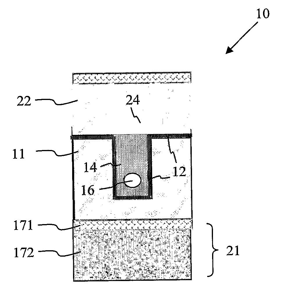
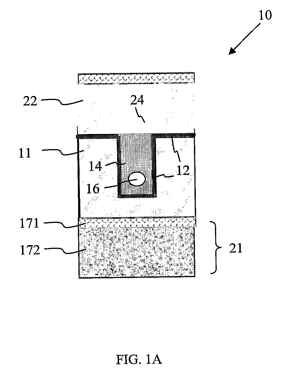
[0022]The microfluidic device according to the invention comprises a base substrate having a recess defined therein. The recess is present in the surface of the base substrate, defined by at least two opposing lateral walls and a base wall. Depending on the configuration desired, the recess may be defined (laterally) across the entire length / width of the base substrate (i.e. from one edge to another edge), or it may be defined near one edge of the base substrate. Also possible is that it is defined near the middle portion of the substrate so as to accommodate the fabrication of other fluid structures around it on the base substrate. In certain embodiments, for example where a through-recess spanning the entire surface or length (e.g. from end to end) of the base substrate is required, the recess is bounded by 1 pair of opposing lateral walls formed along the length of the channel and a base wall, while the ends of the recess are lateral openings not bounded by any lateral wall. Where the recess is formed to have one end defined at one edge of the base substrate and the other end terminating away from the edge of the base substrate (e.g. at the middle portion), then the recess is bounded by 1 pair of opposing lateral walls, 1 base wall, and 1 lateral wall connecting the two opposing lateral walls and opposing a lateral opening. Where the recess is defined entirely within the base substrate, the recess is then defined by 2 pairs of opposing lateral walls and a base wall.
[0023]The recess may have any suitable shape, such as a cuboid shape (e.g. rectangular or square shaped), in which case the recess is in the shape of a trench. Alternatively, it may be semi-cylindrical or hemispherical, or any other suitable
irregular shape. Regardless of the shape, the depth of the recess may range from about 0.1 μm to about 10 μm if small channels are desired, or more typically between about 6 to 8 μm. For some embodiments requiring large channels or for achieving certain reflow characteristics with certain types of
filling materials, a recess depth of more than 10 μm may be used to accommodate the larger channel. Apart from the depth, the width of the recess may also be sized according to the
diameter of the channel it is required to accommodate, and may range from about 0.2 microns to about 5 microns.
[0024]Where a hemispherical, or semi-cylindrical shaped recess is formed in the base substrate, it is to be noted that the recess is then defined by a continuous wall. In this case, any two directly opposing end portions of the hemispherical walls of the recess may be considered to be any opposing lateral walls in the recess as defined by the plane of the openings at each of the two ends of a straight channel. The same applies to an irregularly shaped recess.
[0025]The recess present in the substrate serves to receive filling material for forming a filler member within the recess. The filler member is arranged such that at least a portion of it occupies the recess. This means that the filler member may be entirely present within the recess, or a portion of it may extend outside of the recess to cover a part of the top surface of the base substrate. Typically, deposition of filling material into the recess to form the filler member results in some of the filling material being deposited outside of the recess. If preferred, this extraneous filling material may be removed so that the filling material is present only within the recess.

