
Clot removal system and method

a clot and clot technology, applied in the field of clot removal system, can solve the problems of obstructing critical blood flow, affecting the life of patients, and damage to tissues,

Active Publication Date: 2013-08-29
COOK MEDICAL TECH LLC
View PDF5 Cites 70 Cited by
  • Summary
  • Abstract
  • Description
  • Claims
  • Application Information

AI Technical Summary

Benefits of technology

The patent describes a clot removal system that includes a sheath and a catheter with a divided distal segment consisting of wall segments with curved configurations. The system has a transport configuration where the distal segment of the catheter is aligned with the sheath and the wall segments are urged against the curved configuration. The system is then advanced to a deployed configuration where the distal segment of the catheter is extended beyond the sheath and the wall segments conform to the curved configuration. The clot removal system has scraping edges that help remove the clot from the patient's vessel wall. The technical effect of this system is the ability to efficiently and safely remove clots from blood vessels.

Problems solved by technology

This partially or completely blocked blood flow may prevent normal blood flow and oxygen from reaching certain tissues and, thus, may result in damage to the tissues.
If a clot becomes dislodged from the vessel walls it may travel to other portions of the vascular system, where it may ultimately occlude critical blood flow.
Regardless of the particular location of the clot within the vascular system, clots consisting of blood or other substances, if left untreated, may cause serious damage and, in some cases, may become life threatening.
While rotation and / or axial movement of the tined catheter may break up the clot into smaller pieces, the distal tips of the finger-like tines may potentially damage the vessel walls, particularly during reciprocating axial movement.
A number of additional risks are associated with clot removal procedures, including risks associated with the use of thrombolytic agents and risks associated with the migration of dislodged portions of the clot.

Method used


Image

  • Clot removal system and method
  • Clot removal system and method
  • Clot removal system and method

Examples


Embodiment Construction

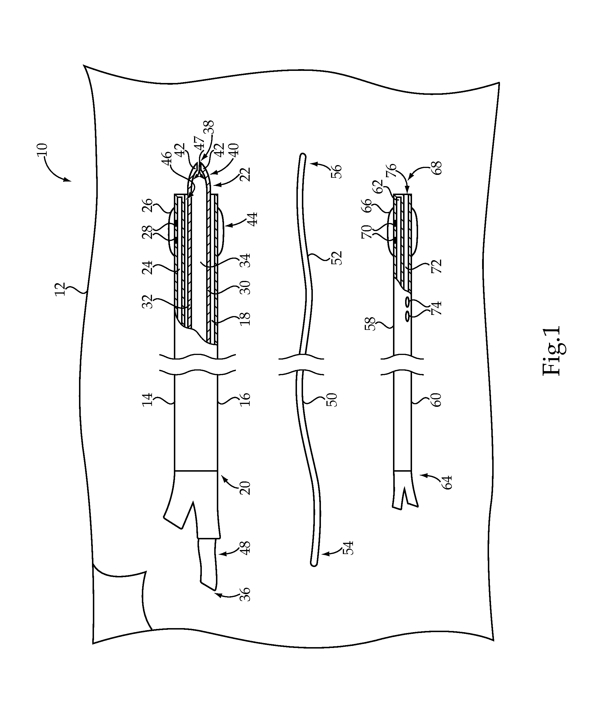
[0015]Referring to FIG. 1, there is shown a clot removal system 10 according to one embodiment of the present disclosure. The clot removal system 10 may include a number of components, which may be provided within a sterile, tear open package 12, as is known in the art. In performing a clot removal procedure on a patient, some or all of the components of the clot removal system 10 may be used, depending upon the specifics of the procedure to be performed. As should be appreciated, however, the components shown in FIG. 1 might be separately packaged and / or the clot removal system 10 might also include components in addition to those shown, including components routinely used in percutaneous vascular procedures.

[0016]The clot removal system 10 generally includes an elongated tubular sheath 14. The sheath 14 may include an elongated tubular body 16 defining at least one device lumen 18 extending from an open proximal end 20 to an open distal end 22 of the elongated tubular body 16. The...


PUM


Abstract

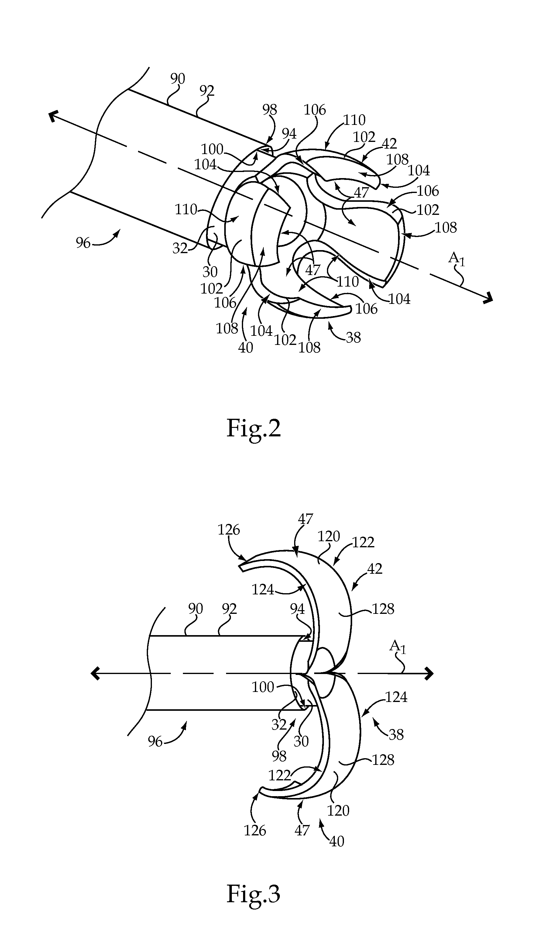
A clot removal system includes an elongated tubular sheath and an elongated tubular catheter received within the sheath. A distal segment of the catheter is split into a plurality of catheter wall segments, with each wall segment having a pre-shaped curved configuration. Each wall segment defines at least one scraping edge and has a distal tip that is less stiff than a remaining portion of the wall segment. The clot removal system has a transport configuration in which the distal segment of the catheter is axially aligned with a distal segment of the sheath and the wall segments are urged against the pre-shaped curved configuration by the sheath. The clot removal system also has a deployed configuration in which the distal segment of the catheter is advanced distally beyond the distal segment of the sheath and the wall segments conform to the pre-shaped curved configuration.

Description

RELATION TO OTHER PATENT APPLICATION[0001]This application claims priority to provisional patent application 61 / 602,696, filed Feb. 24, 2012, with the same title.TECHNICAL FIELD[0002]The present disclosure relates generally to a clot removal system having an elongated tubular catheter received within an elongated tubular sheath, and more particularly to a catheter that is distally split into a plurality of catheter wall segments having pre-shaped curved configurations.BACKGROUND[0003]Thrombosis is the formation of a thrombus, or blood clot, within the vascular system of a patient. A blood clot typically occurs when blood hardens from a liquid to a solid. When attached to vessel walls, blood clots, and other substances, such as plaque or fat, may reduce or block blood flow downstream from the clot. This partially or completely blocked blood flow may prevent normal blood flow and oxygen from reaching certain tissues and, thus, may result in damage to the tissues. If a clot becomes dis...

Claims


Application Information

Patent Timeline
IPC IPC(8): A61M25/10A61M25/09
CPCA61M25/104A61M25/09A61B17/22031A61B2017/2215A61B17/320725A61B2017/22084A61B2017/00867
Inventor TEKULVE, KURT
Owner COOK MEDICAL TECH LLC
Learn More