Femoral guide for knee surgery

a femoral guide and knee technology, applied in the field of new and improved methods of performing surgery, can solve the problems of soft tissue in the knee, difficult access to posterior soft tissue to remove bone spurs (ostified), ligaments in the back of the joint, surgeons may be very reluctant, or at least very careful, of inserting instruments into the back of the knee joint, etc., to facilitate the balancing of ligaments and facilitate the effect of knee portion balancing

a femoral guide and knee technology, applied in the field of new and improved methods of performing surgery, can solve the problems of soft tissue in the knee, difficult access to posterior soft tissue to remove bone spurs (ostified), ligaments in the back of the joint, surgeons may be very reluctant, or at least very careful, of inserting instruments into the back of the knee joint, etc., to facilitate the balancing of ligaments and facilitate the effect of knee portion balancing

US20130226185A1Inactive Publication Date: 2013-08-29BONUTTI SKELETAL INNOVATIONS

Image

  • Femoral guide for knee surgery
  • Femoral guide for knee surgery
  • Femoral guide for knee surgery

Examples


Embodiment Construction

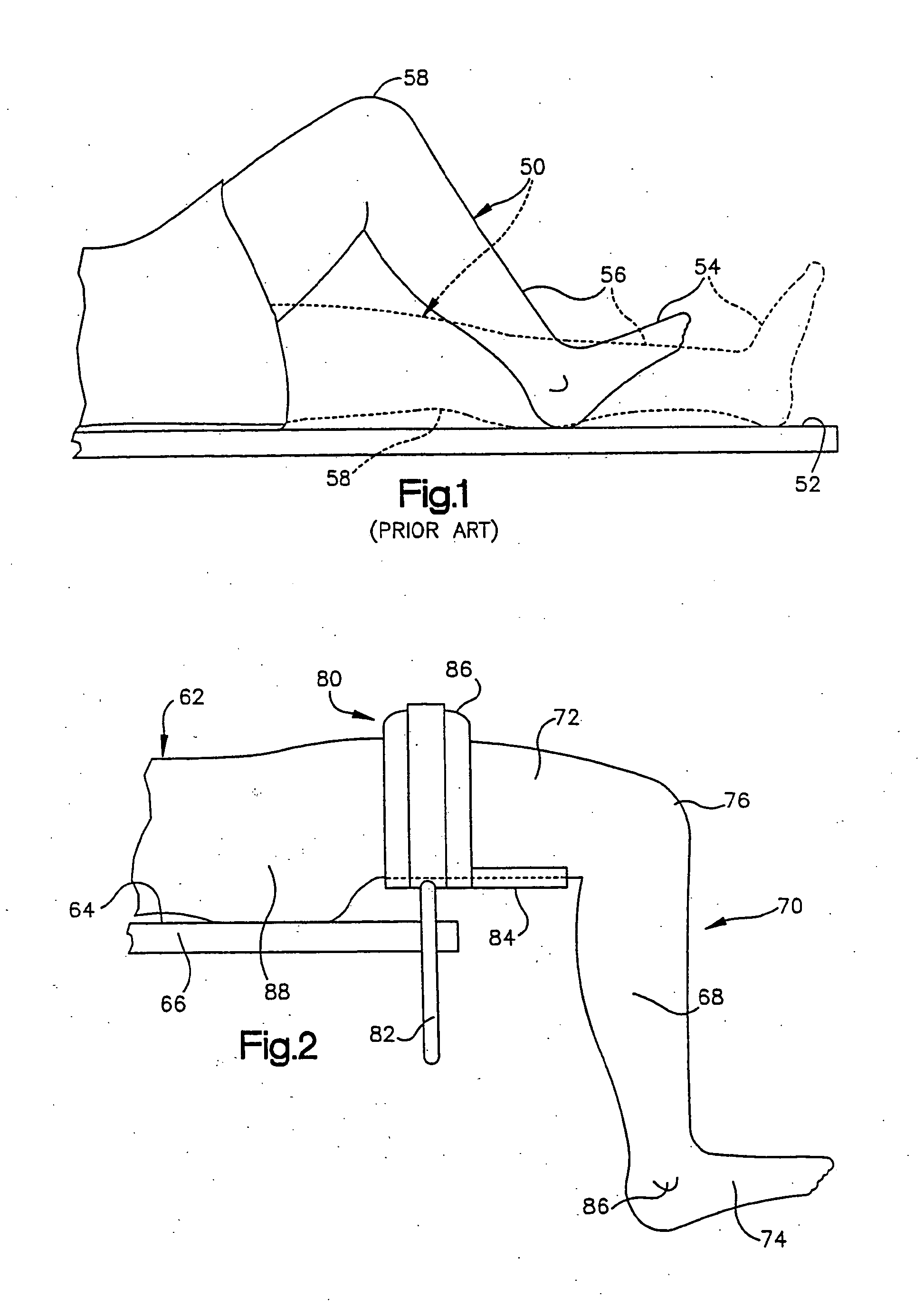
Known Method of Performing Surgery on a Patient's Knee

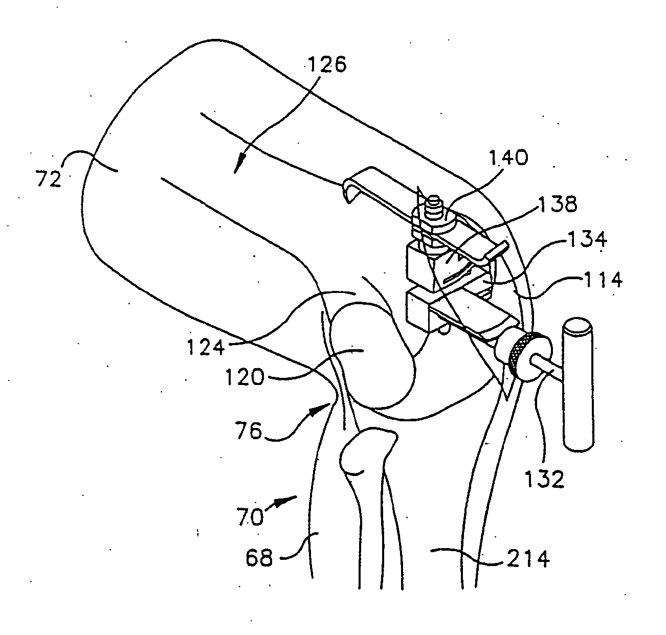
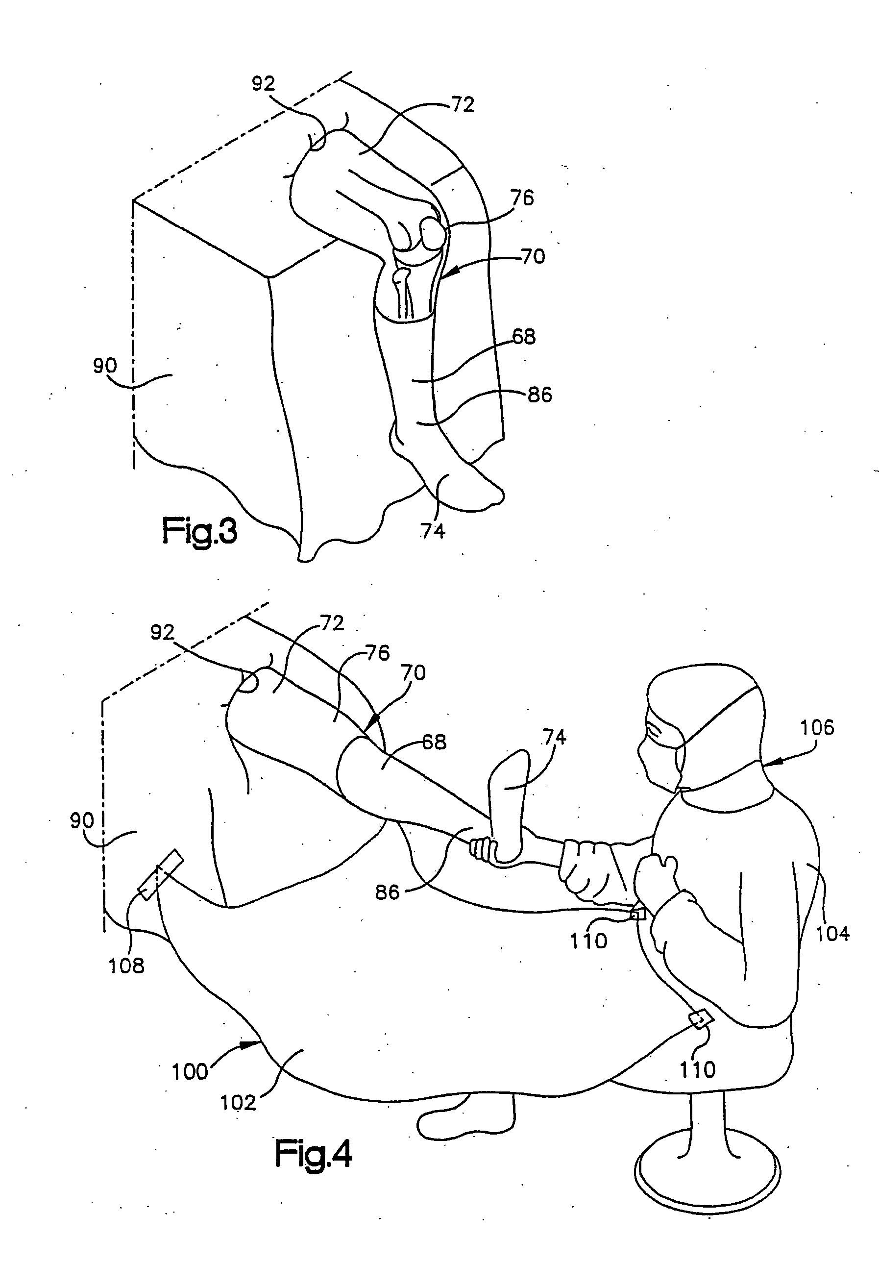
[0131]During the performance of surgery using known methods, a patient is supported on an operating table or other support surface 52 (FIG. 1). When a leg 50 of the patient is in the extended position illustrated in dashed lines in FIG. 1, a foot 54 connected with a lower portion 56 of the leg 50 is disposed above the support surface 52. During an operation on a knee portion 58 of the leg 50, the knee portion is raised and lowered relative to the support surface as the leg 50 is flexed and extended. However, the foot 54 is always disposed above the support surface 54 and may be supported by the support surface throughout the operation.

[0132]During this known operating procedure, an incision is made in the knee portion 58 of the leg 50 when the leg is in the extended position illustrated in dashed lines in FIG. 1. At this time, the foot 54 of the patient may rest on the support surface 52 or be disposed in a foot support located a...


PUM

PropertyMeasurementUnit
perimeteraaaaaaaaaa
polymericaaaaaaaaaa

Abstract

A joint replacement kit for use in a joint replacement procedure replacing a portion of a body joint. The kit includes a cutting guide and a trial component wherein the cutting guide and trial component are packaged together. There is also provided a method for replacing a portion of a body joint. The method includes providing a joint replacement kit having a cutting guide and a trial component, positioning the cutting guide against an end portion of a bone, cutting the end portion of the bone with a cutting instrument, positioning the trial component to the cut end portion of the bone, and disposing of the cutting guide and trial component.

Description

CROSS-REFERENCE TO RELATED APPLICATIONS[0001]This application is a continuation of U.S. patent application Ser. No. 10 / 888,783 filed Jul. 9, 2004, which is a continuation of U.S. patent application Ser. No. 10 / 191,751 filed Jul. 8, 2002 (now U.S. Pat. No. 7,104,996); which is a continuation-in-part of each of the following: U.S. patent application Ser. No. 09 / 976,396 filed Oct. 11, 2001 (now U.S. Pat. No. 6,770,078); U.S. patent application Ser. No. 09 / 941,185 filed Aug. 28, 2001 (now U.S. Pat. No. 6,702,821); U.S. patent application Ser. No. 09 / 566,070 filed May 5, 2000 (now U.S. Pat. No. 6,575,982); U.S. patent application Ser. No. 09 / 737,380 filed Dec. 15, 2000 (now U.S. Pat. No. 6,503,267); U.S. patent application Ser. No. 09 / 569,020 filed May 11, 2000 (now U.S. Pat. No. 6,423,063); U.S. patent application Ser. No. 09 / 483,676 filed Jan. 14, 2000 (now U.S. Pat. No. 6,468,289); U.S. patent application Ser. No. 09 / 798,870 filed Mar. 1, 2001 (now U.S. Pat. No. 6,503,277); U.S. paten...

Claims


Application Information

Patent Timeline
29 Aug 2013
Publication
US20130226185A1
IPC
A61B17/15; A61B17/04
CPC
A61B17/025; A61B17/0401; A61B17/0487; A61B17/155; A61B17/157; A61B17/158; A61B17/1604; A61B17/1666
Inventors
BONUTTI, PETER M.