Methods, devices, and systems for percutaneously anchoring annuloplasty rings

a technology of annuloplasty and percutaneous anchoring, which is applied in the field of percutaneous transcatheter repair of heart valves, can solve the problems of patient to a high risk of infection, prevent the valve from sealing properly, and long recovery tim

Active Publication Date: 2013-08-29
VALCARE INC
View PDF4 Cites 206 Cited by
  • Summary
  • Abstract
  • Description
  • Claims
  • Application Information

AI Technical Summary

Problems solved by technology

This causes the valve opening to enlarge, which prevents the valve from sealing properly.
The procedure can expose the patient to a high risk of infection and may result in a long and difficult recovery.
The recovery can be particularly difficult for patients in less than optimal health due to the effects of suffering from a heart valve defect such as regurgitation.

Method used


Image

  • Methods, devices, and systems for percutaneously anchoring annuloplasty rings
  • Methods, devices, and systems for percutaneously anchoring annuloplasty rings
  • Methods, devices, and systems for percutaneously anchoring annuloplasty rings

Examples


example ring embodiments

with Separately Deployed Anchors

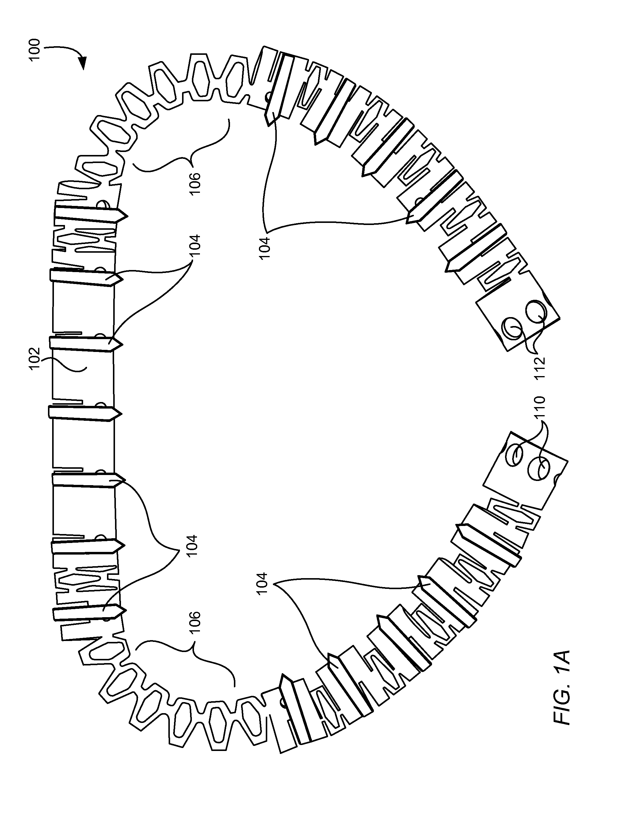
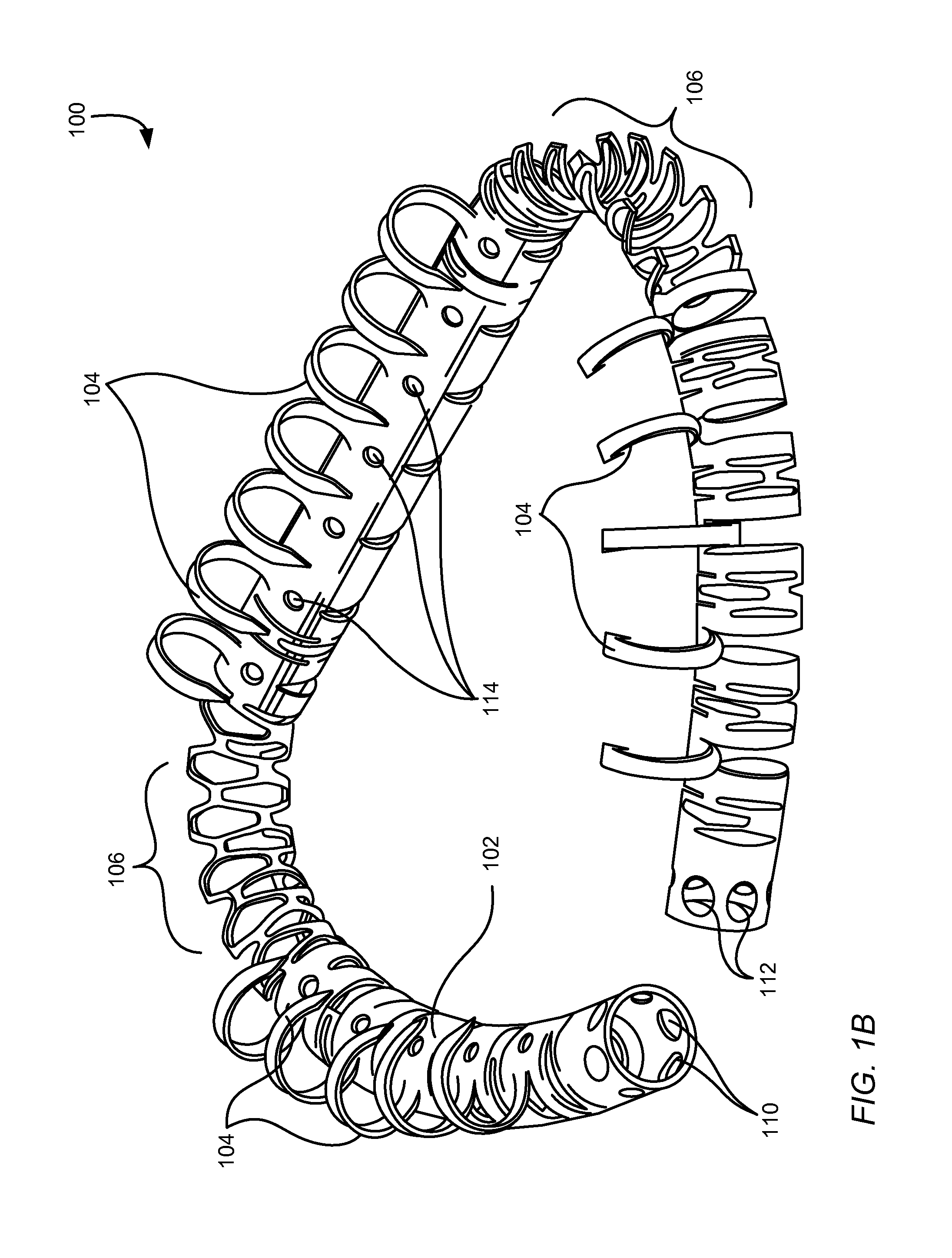
[0101]FIG. 8A is top view of an annuloplasty ring 800 in an operative geometry according to certain embodiments. The annuloplasty ring 800 illustrated in FIG. 8A is in an annular (D-shaped) operable geometry in a contracted state. The annuloplasty ring 800 is configured to enable percutaneous, transcatheter annuloplasty repair of a heart valve. The annuloplasty ring 800 may be fastened, percutaneously, to the annulus of the heart valve while in the expanded state and then reduced to the contracted state to decrease an A-P distance of the target valve and thereby improve leaflet coaptation of the target valve and reduce regurgitation through the target valve.

[0102]The annuloplasty ring 800 includes a body member 802 having a plurality of anchors 804, a plurality of anchor regions 806a, 806b, 806c (collectively 806), a plurality of expansion regions 808a, 808b (collectively 808), a plurality of anchor windows 810, a ring closure lock 812, and a pivot 81...

example anchor

Shapes and Designs

[0136]FIG. 13 is a view of various anchor shapes that may be used with the disclosed trans-catheter annuloplasty rings. Anchor shapes 1300, 1320, and 1330 have curved geometries and may be formed from superelastic material, such as Nitinol, so that they self-propel into annulus tissue. The variations in curvature and shape allow for the anchors to deploy into the annular tissue at differing depths. Anchor shape 1310 has a “wavy” geometry. The wave shape gives better grip into the tissue in certain environments. Anchor shape 1340 has a straight geometry and may be propelled into annular tissue through application of mechanical force (e.g., by inflating a balloon behind anchor 1340 or in the center of the annuloplasty ring). Artisans will recognize from the disclosure herein that combinations of barb designs and / or deployed configurations may also be used. In some embodiments, all of the anchors of an annuloplasty rings are of the same shape. In other embodiments, an...

example deployment embodiments

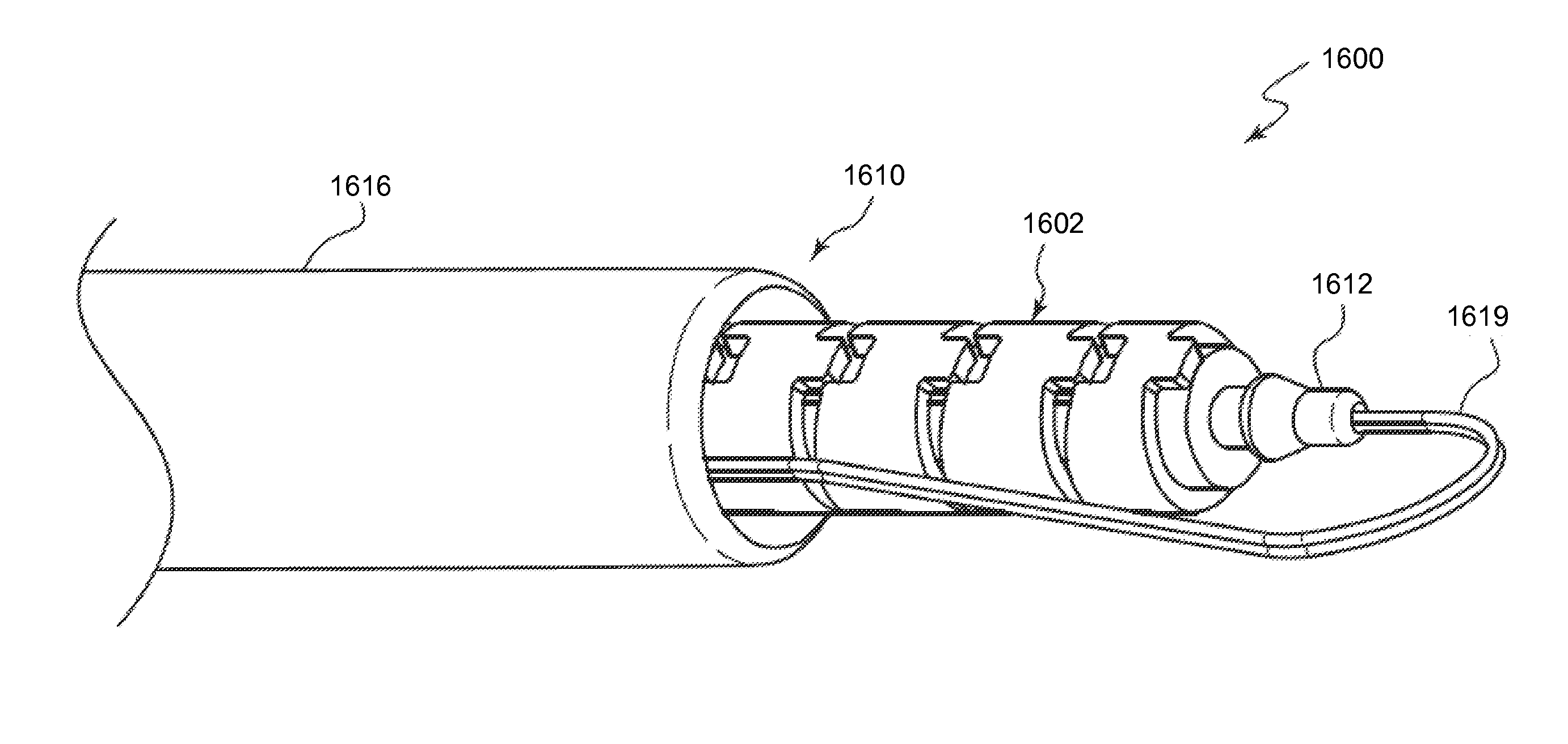
[0138]As discussed above, the annuloplasty ring embodiments disclosed herein are configured for percutaneous transcatheter delivery and fixation to heart valves. The annuloplasty rings may be delivered through a catheter to the mitral valve, for example, using a trans-septal approach, a retrograde approach, or a trans-apical approach. For example, FIG. 15A is a schematic diagram illustrating a trans-septal approach for endovascular delivery of an annuloplasty ring (not shown) to the mitral valve 1510 of a heart 1500 according to one embodiment. For illustrative purposes, a partial cross-section of the heart 1500 is illustrated to show the right atrium RA, right ventricle RV, left atrium LA, and left ventricle LV. For clarity, certain features (e.g., papillary muscles and chordae tendineae) are not shown. In the trans-septal approach shown in FIG. 15A, the left atrium LA is approached by advancement of a catheter 1512 through the inferior vena cava 1514, into the right atrium RA, acr...


PUM


Abstract

Apparatus, systems, and methods are provided for percutaneous transcatheter delivery and fixation of annuloplasty rings to heart valves. An annuloplasty ring includes an outer tube, an inner body member, and an anchor deployment system. The outer tube includes a plurality of windows and has an axis along its length. The internal body member includes a plurality of anchors formed perpendicular to the axis. The anchor deployment system selectively rotates the internal body member with respect to the axis of the outer tube. The rotation deploys the plurality of anchors through the plurality of windows.

Description

RELATED APPLICATIONS[0001]This application claims the benefit under 35 U.S.C. §119(e) of U.S. Provisional Patent Application No. 61 / 734,904, filed Dec. 7, 2012, titled “ROTATIONAL BARBS,” and is a continuation-in-part of U.S. patent application Ser. No. 13 / 779,478, filed Feb. 27, 2013, titled “PERCUTANEOUS ANNULOPLASTY SYSTEM WITH ANTERIOR-POSTERIOR ADJUSTMENT,” which claims the benefit under 35 U.S.C. §119(e) of U.S. Provisional Patent Application No. 61 / 604,856, filed Feb. 29, 2012, titled “PERCUTANEOUS ANNULOPLASTY SYSTEM WITH ANTERIOR POSTERIOR ADJUSTMENT,” and of U.S. Provisional Patent Application No. 61 / 734,904, each of which is hereby incorporated by reference herein in its entirety.TECHNICAL FIELD[0002]The present disclosure relates to treating and repairing heart valves, and specifically to apparatus, systems, and methods for percutaneous transcatheter repair of heart valves. Disclosed embodiments include adjustable annuloplasty rings that are configured to be delivered th...

Claims


Application Information

Patent Timeline
Patent Type & Authority Applications(United States)
IPC IPC(8): A61F2/24
CPCA61F2/2448A61F2/2466A61F2220/0016A61F2/2427
Inventor YELLIN, NADAVSHAOLIAN, SAMUEL M.DUMONTELLE, JEFFREY P.
Owner VALCARE INC
Why Eureka
Try Eureka