Method and Device for Yarn Braking Especially at Renewal of Spinning in a Working Position of an Air Jet Spinning Machine

Active Publication Date: 2013-09-05
MASCHINENFABRIK RIETER AG
View PDF2 Cites 0 Cited by
  • Summary
  • Abstract
  • Description
  • Claims
  • Application Information

AI Technical Summary

Benefits of technology

The invention relates to a braking device for vehicles. It has the advantage of easy regulation of braking force through a control member. The device also includes a pneumatic cylinder with a pressure regulator for precise and reliable functioning. The contact surfaces of the brake friction members are spherical, which enables easy swinging of the moving brake friction member in case of need. The stationary brake friction member is formed by a cylinder against which the moving brake friction member abuts upon braking. The brake friction member also includes a plane braking surface that increases the braking effect.

Problems solved by technology

By the effect of the magnetic force, the brake friction members pull to each other and clamp the yarn with the set force, which causes braking of the yarn.
The disadvantage of both the method and the device according to CZ 2007-629 A3 lies in the fact that the braking force is constant for one yarn diameter and it is difficult to change it when, in case it is needed technologically, yarn diameter changes.

Method used


Image

  • Method and Device for Yarn Braking Especially at Renewal of Spinning in a Working Position of an Air Jet Spinning Machine
  • Method and Device for Yarn Braking Especially at Renewal of Spinning in a Working Position of an Air Jet Spinning Machine
  • Method and Device for Yarn Braking Especially at Renewal of Spinning in a Working Position of an Air Jet Spinning Machine

Examples


embodiment

OF EMBODIMENT

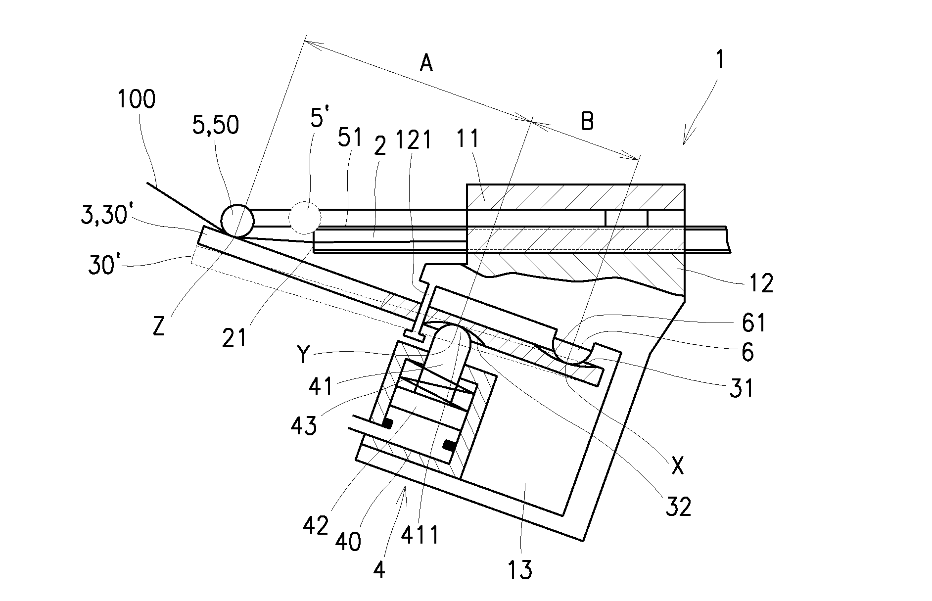
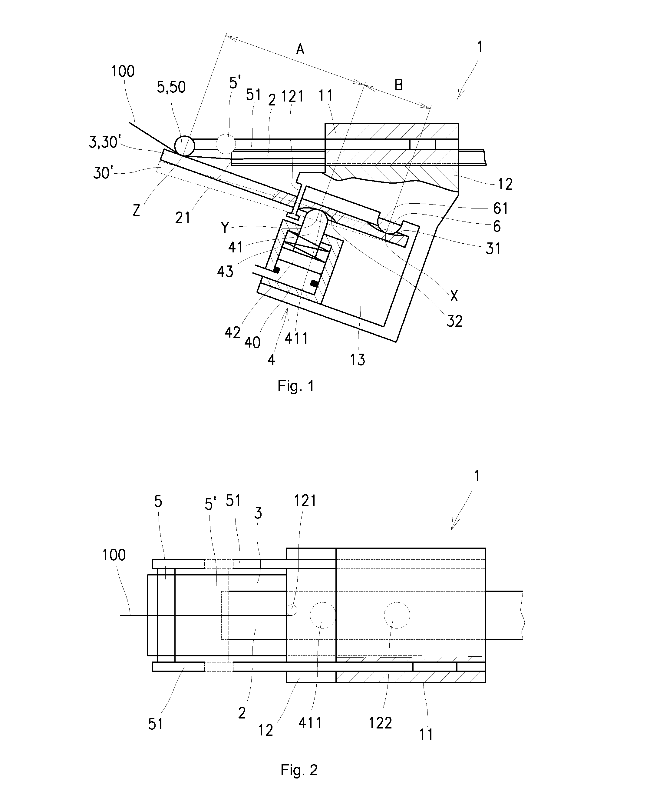
[0030]At the example of embodiment represented in the FIGS. 1 and 2, the device for braking of the yarn is arranged on the attending device of the jet spinning machine, which is arranged displaceably along a line of work positions of the machine and provided with a vacuum tube 2 for sucking-in and subsequent releasing of the end of the yarn 100 for spinning-in. In the attending device on the FIGS. 1 and 2 there is shown a brake body 1 which is in the represented embodiment divided to the upper part 11 and bottom part 12 and between them the vacuum tube 2 is placed. The mouth of the vacuum tube 2 projects beyond the front part of the brake body 1. Above the mouth 21 of the vacuum tube 2 there is the stationary brake friction member 5 arranged, which is placed on the couple of the guiding bars 51, which are placed slidingly in the upper part 11 of the brake body 1 and coupled with a known not depicted drive, e.g. a pneumatic cylinder. The couple of the guiding bars 51 can...


PUM

PropertyMeasurementUnit
Forceaaaaaaaaaa
Pressureaaaaaaaaaa
Lengthaaaaaaaaaa

Abstract

The inventions relates to the method of yarn braking especially at renewal of spinning in a working position of an air jet spinning machine by means of attending a device provided with a vacuum tube (2), into which before commencement of braking there is the end of the yarn (100) sucked in, which at drawing off from the vacuum tube (2) is braked between the braking surfaces of a stationary brake friction member (50) and a moving brake friction member (30), which are arranged on the attending device displaceably to the track of the yarn (100), while for generating the braking force the moving brake friction member (30) moves towards the stationary brake friction member (50) and it fits against it at a contact abscissa (301) or a contact surface (302). To generate the braking force on the moving brake friction member (30) the action force in the loading point (Y) and the reaction force in the stop point (X) is acting, whereas one of these points is to be found at the end of the moving brake friction member (30) lying opposite to the contact abscissa (301) or the contact surface (302) and the second is lying between this member and the contact abscissa (301) or the contact surface (302), while the action force is generated by means of the control member (4) and the reaction force is generated by means of the stop (6), against which the moving brake friction member (30) leans, so that the braking surface of the moving brake friction member (30) always abuts against the braking surface of the stationary brake friction member (5) along the whole length of their contact abscissa (301) or contact surface (302).The inventions also relates to the corresponding device.

Description

TECHNICAL FIELD[0001]The invention relates to a method of yarn braking especially at renewal of spinning in a working position of an air jet spinning machine by means of attending a device provided with a vacuum tube, into which before commencement of braking there is the end of the yarn sucked in, which at drawing off from the vacuum tube is braked between the braking surfaces of stationary brake friction member and moving brake friction member, which are arranged on the attending device displaceably to the path of the yarn, while for generating the braking force the moving brake friction member moves towards the stationary brake friction member and it fits against it at a contact abscissa or a contact surface.[0002]Next to this the invention relates to a device for braking of the yarn especially at renewal of spinning in a working position of an air jet spinning machine by means of attending a device arranged displaceably along a line of working positions of the machine and provid...

Claims


Application Information

Patent Timeline
IPC IPC(8): D01H4/46D01H4/48
CPCB65H59/22D01H4/02D01H4/50D01H4/48B65H2701/31D01H4/46B65H2555/11
Inventor STEPHAN, ADALBERTBURYSEK, MAREK
Owner MASCHINENFABRIK RIETER AG
Why Eureka
Try Eureka