Liquid flow control for film deposition

Active Publication Date: 2013-09-12
MSP
View PDF3 Cites 28 Cited by
  • Summary
  • Abstract
  • Description
  • Claims
  • Application Information

AI Technical Summary

Benefits of technology

[0008]The disclosure also includes a method for controlling liquid flow through an apparatus comprising an orifice and an adjacent flexible diaphragm separated from each other by a gap through which a liq

Problems solved by technology

Accurate liquid flow control is usually more difficult than the accurate control of gas flow due to the relatively low rate of liquid flow ne

Method used


Image

  • Liquid flow control for film deposition
  • Liquid flow control for film deposition
  • Liquid flow control for film deposition

Examples


Example

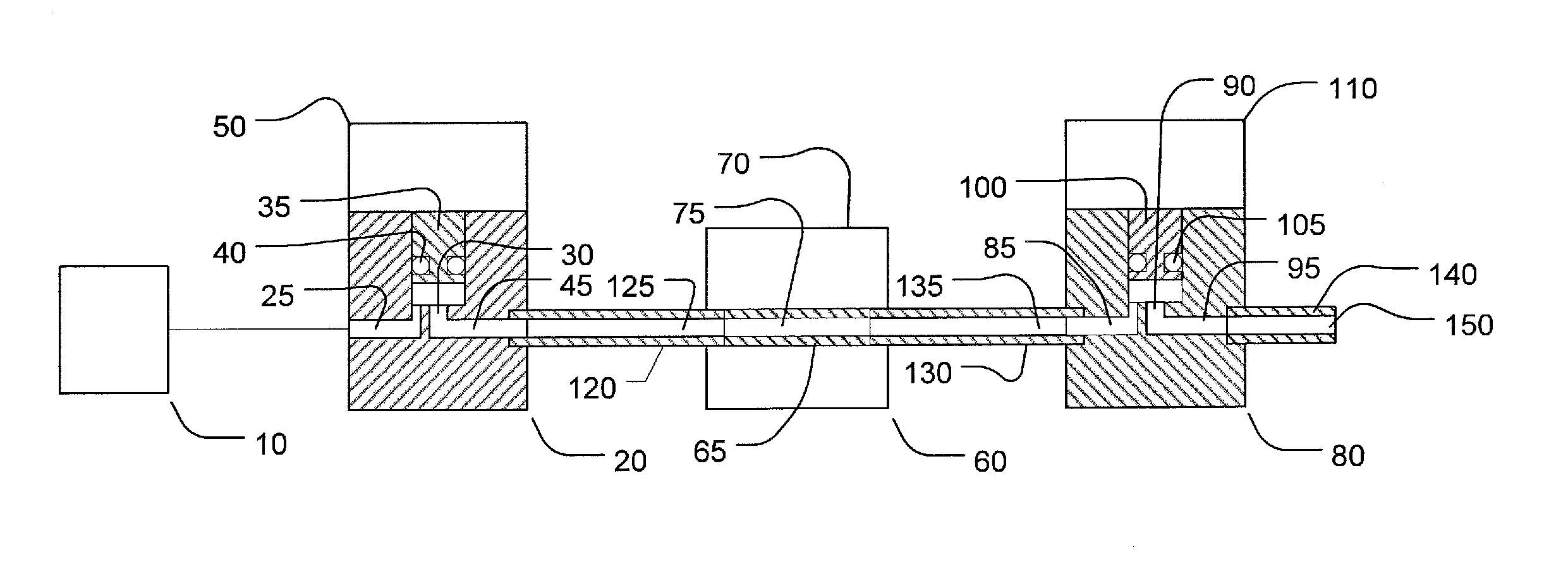
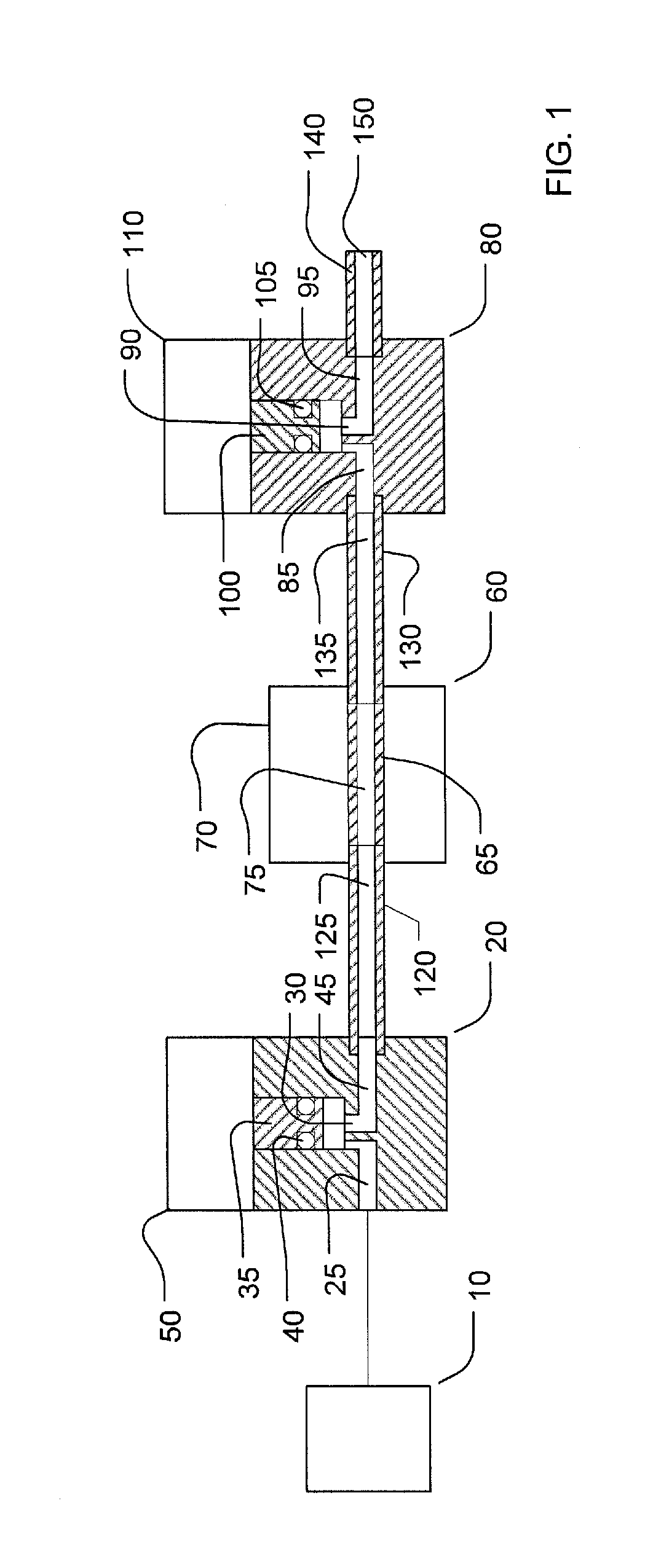
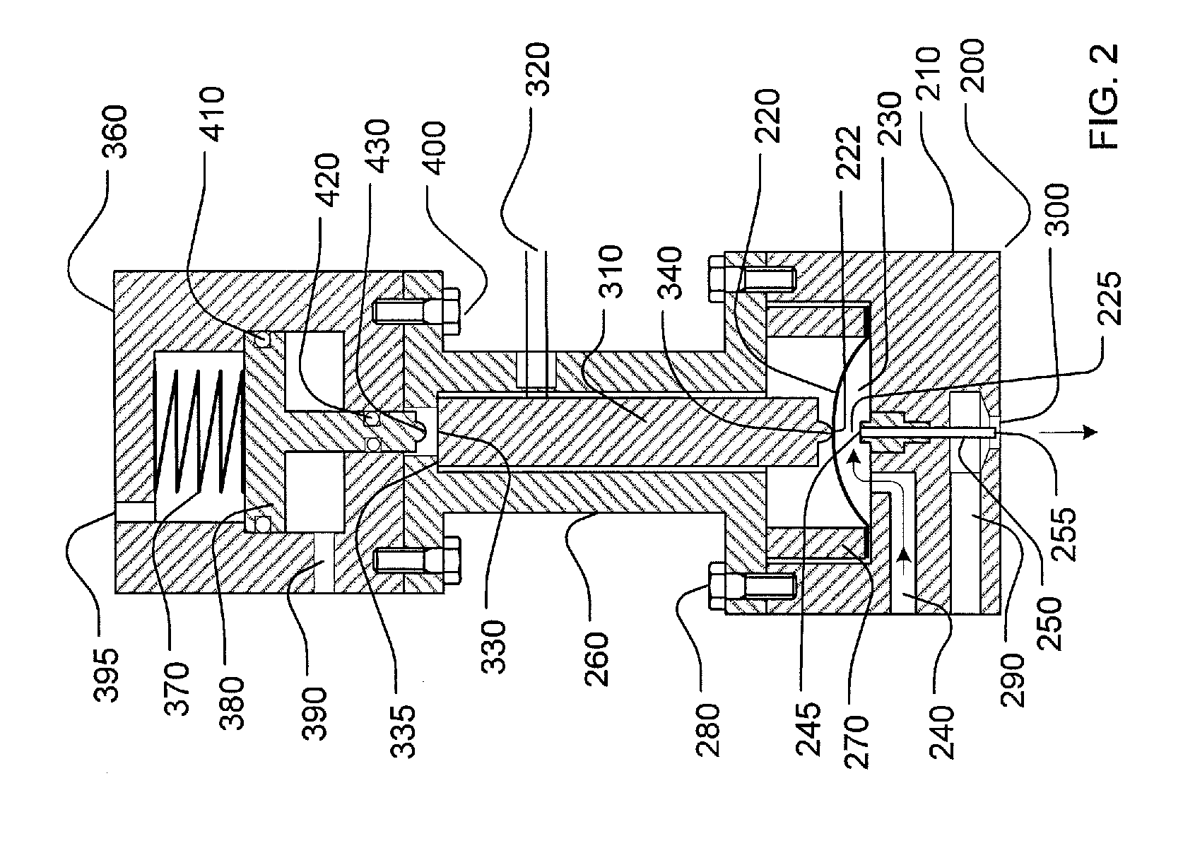
[0012]FIG. 1 is a schematic diagram of a conventional system for liquid flow control in semiconductor applications. FIG. 2 is a schematic diagram of a liquid flow control and liquid shutoff apparatus of the present disclosure in its preferred embodiment. Like reference characters will be used for like elements throughout the figures.

[0013]In the conventional system shown in FIG. 1, a source of liquid, 10, under pressure is connected to a liquid shutoff valve, shown generally located at 20. Downstream of the liquid shutoff valve is a liquid flow sensor, shown generally at 60 and a liquid flow control valve, shown generally at 80. All parts of the system are connected by small-diameter tubing as shown in FIG. 1. The connecting tubing is typically made of stainless steel.

[0014]Shutoff valve 20 generally includes an inlet flow passageway, 25, for liquid from source 10 to flow into the valve, a flow control orifice, 30, a movable solid member, 35, with an O-ring seal 40 for liquid shutof...


PUM


Abstract

An apparatus for controlling liquid flow wherein the apparatus comprises an orifice and an adjacent flexible diaphragm separated from each other by a gap through which a liquid flows. The diaphragm is sufficiently flexible to vary the gap thereby controlling the rate of liquid flowing through the orifice or to provide a positive liquid shutoff of liquid flowing through the orifice. A method for controlling liquid flow through the apparatus comprises flexing said diaphragm to vary a size of the gap to control the rate of liquid flowing through the orifice or to provide a positive liquid shutoff of liquid from flowing through the orifice.

Description

CROSS REFERENCE TO RELATED APPLICATIONS[0001]The present application is based on and claims the benefit of U.S. provisional patent application Ser. No. 61 / 609,616, filed Mar. 12, 2012, the content of which is hereby incorporated by reference in its entirety.BACKGROUND OF THE DISCLOSURE[0002]Thin film deposition for semiconductor device fabrication is generally accomplished through a gas phase process, such as chemical vapor deposition (CVD), plasma enhanced deposition (PECVD) or atomic layer deposition (ALD). The process is typically carried out in a deposition chamber under vacuum conditions with the substrate being exposed to the precursor vapor at an elevated temperature to form thin film. If the precursor chemical is a liquid at room temperature the precursor liquid must first be vaporized to generate vapor to form the desired thin film.[0003]Modern semiconductor device fabrication typically uses a liquid-source vaporization apparatus to generate vapor for thin film deposition. ...

Claims


Application Information

Patent Timeline
IPC IPC(8): H01L21/02
CPCH01L21/02104F16K31/007F16K7/14F16K31/1221Y10T137/0357Y10T137/7722Y10T137/7759H01L21/205
Inventor DINH, THUC M.LIU, BENJAMIN Y.H.MA, YAMIN
Owner MSP
Why Eureka
Try Eureka