Device for controlling assembled battery

a technology for assembled batteries and battery cells, applied in the direction of electrochemical generators, instruments, transportation and packaging, etc., can solve the problems of long time needed and the inability to predict the time when the assembled battery becomes abnormal

Active Publication Date: 2013-09-12
NISSAN MOTOR CO LTD
View PDF5 Cites 37 Cited by
  • Summary
  • Abstract
  • Description
  • Claims
  • Application Information

AI Technical Summary

Benefits of technology

[0007]According to the invention, it is possible to more precisely grasp the tendency of a change in voltage difference or a change in SOC difference, and whereby it is possible to appropriately predict time when the assembled battery becomes an abnormal state.

Problems solved by technology

This leads to the problem of a long time needed to detect that the assembled battery is in a state substantially corresponding to an abnormal state.
Also, this leads to another problem that it is possible to detect the assembled battery being in a state substantially corresponding to an abnormal state, but it is impossible to predict time when the assembled battery becomes an abnormal state.

Method used


Image

  • Device for controlling assembled battery
  • Device for controlling assembled battery
  • Device for controlling assembled battery

Examples


first embodiment

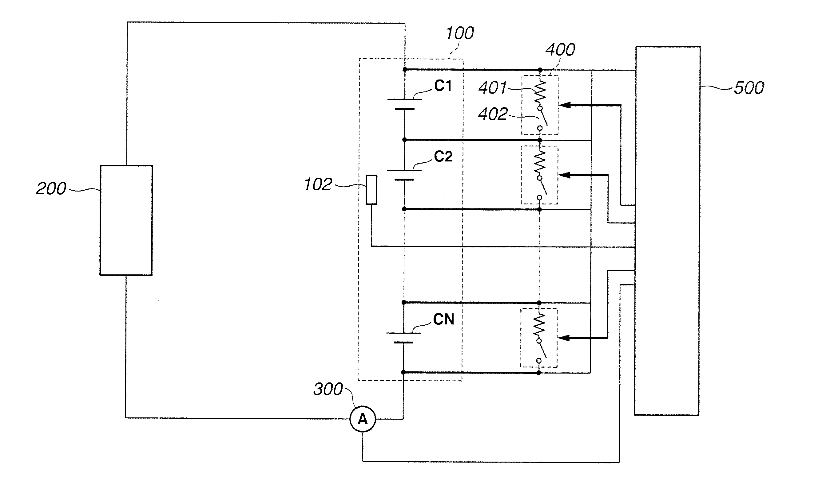
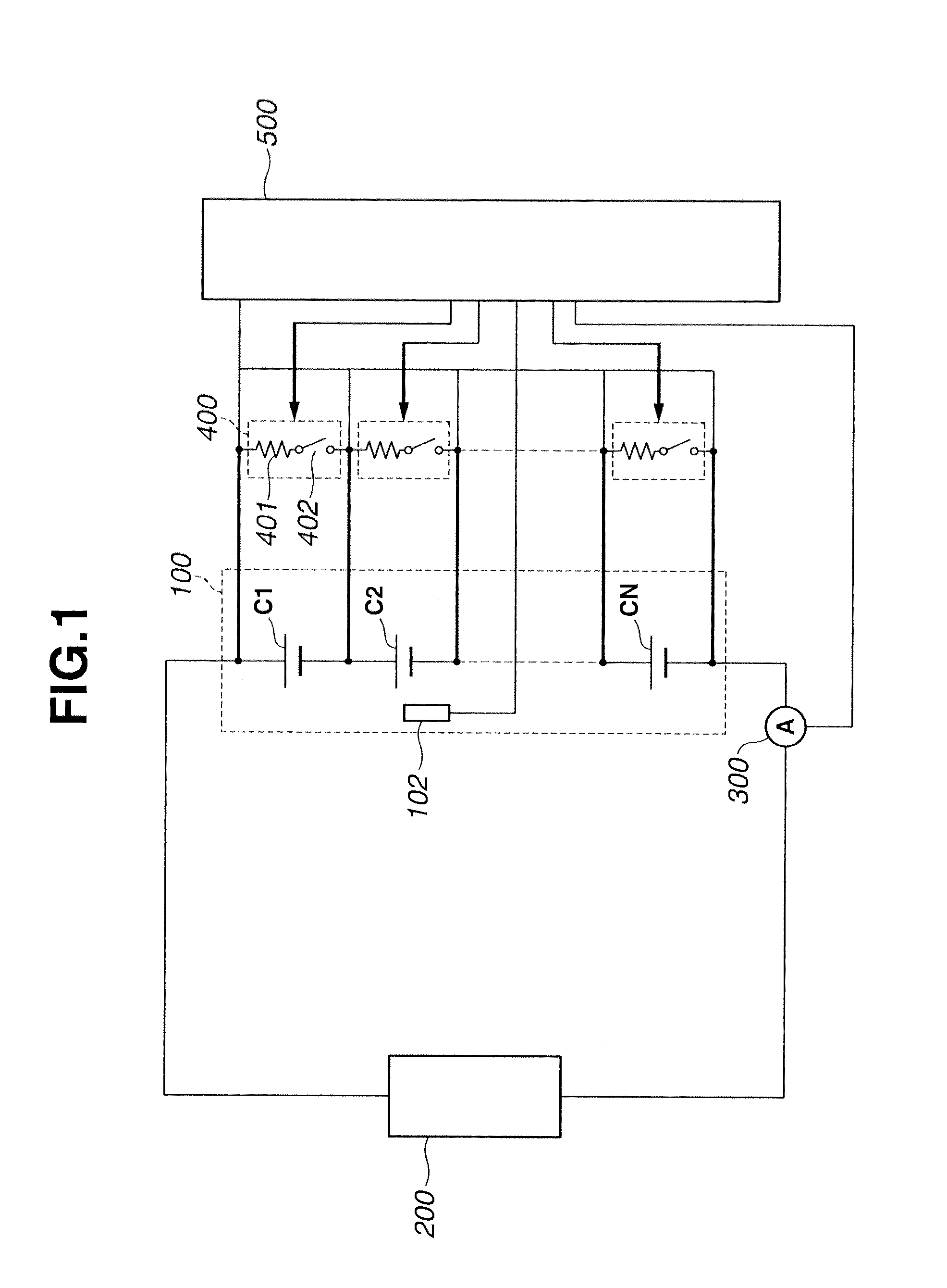
[0025]FIG. 1 is the system diagram illustrating an assembled battery system of the embodiment. The assembled battery system of the embodiment is hereunder exemplified in a battery for use in an automotive vehicle such as a hybrid vehicle, an electric vehicle or the like.

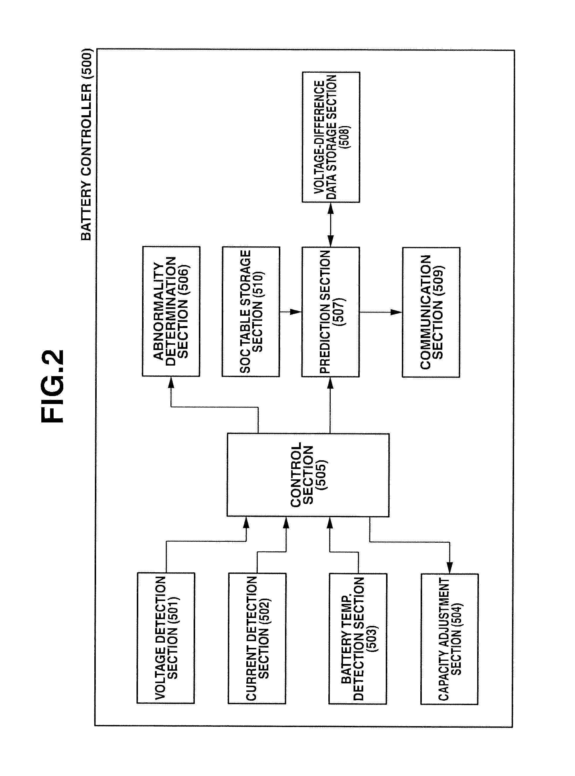
[0026]As shown in FIG. 1, the assembled battery system of the embodiment is comprised of an assembled battery 100 provided with a plurality of single batteries C1, C2, . . . , CN, connected in series with each other, a load 200 electrically connected to both ends of the assembled battery 100, capacity adjustment circuits 400 for adjusting a capacity of the assembled battery 100, and a battery controller 500 for controlling the whole assembled battery system.

[0027]Assembled battery 10 is constructed by connecting single batteries C1, C2, . . . , CN, whose number N is an integer, in series. An alkaline storage battery such as a nickel-hydrogen battery cell or an organic electrolyte secondary battery such as a lithium-i...

second embodiment

[0074]Next, the second embodiment of the invention is hereunder described.

[0075]The second embodiment is similar to the first embodiment except that, in the assembled battery system shown in FIGS. 1-2, abnormality-time prediction processing is executed by a method described below.

[0076]The abnormality-time prediction processing of the second embodiment is hereinafter described.

[0077]FIGS. 8-9 are the flowchart illustrating the flow of the abnormality-time prediction processing of the second embodiment. The abnormality-time prediction processing, hereinafter described in detail, is initiated when turning on an ignition switch of the vehicle, on which the assembled battery system of the second embodiment is mounted, or when powering the vehicle's electrical systems by the charging-on system. The following processing is executed mainly by means of the prediction section 507 of the battery controller 500.

[0078]First, at step S101, in the same manner as the previously-discussed step S1 o...

third embodiment

[0098]Next, the third embodiment of the invention is hereunder described.

[0099]The third embodiment is similar to the first embodiment except that, in the assembled battery system shown in FIGS. 1-2, abnormality-time prediction processing is executed by a method described below.

[0100]The abnormality-time prediction processing of the third embodiment is hereinafter described.

[0101]FIG. 13 is the flowchart illustrating the flow of the abnormality-time prediction processing of the third embodiment. The abnormality-time prediction processing, hereinafter described in detail, is initiated when turning on an ignition switch of the vehicle, on which the assembled battery system of the third embodiment is mounted, or when powering the vehicle's electrical systems by the charging-on system. The following processing is executed mainly by means of the prediction section 507 of the battery controller 500.

[0102]First, at step S301, in the same manner as the previously-discussed step S1 of the fi...


PUM


Abstract

In a device for controlling an assembled battery provided with a plurality of single batteries, the device includes a capacity adjustment section for adjusting a capacity such that voltages of the single batteries are equalized at a targeted voltage, an internal state detection section for detecting terminal voltages or SOC of the single batteries and for detecting, based on the detected terminal voltages/SOC, a voltage/SOC difference among the single batteries as voltage-difference/SOC-difference data, and a time-series data storage for storing the voltage-difference/SOC-difference data in time-series. Also provided is a prediction section for more appropriately predicting time when the assembled battery becomes an abnormal state, based on a time-dependent change in the voltage-difference/SOC-difference data detected in a voltage/SOC region different from the targeted voltage by a predetermined voltage, among the stored time-series voltage-difference/SOC-difference data.

Description

TECHNICAL FIELD[0001]The present invention relates to a device for controlling an assembled battery provided with a plurality of single batteries.BACKGROUND ART[0002]Regarding an assembled battery provided with a plurality of single batteries, technologies to perform a capacity adjustment of the plurality of single batteries constructing the assembled battery are generally known. For example, Patent document 1 proposes a technology for detecting that the assembled battery is in a state substantially corresponding to an abnormal state when a time interval, during which a capacity adjustment is executed, becomes less than or equal to a predetermined threshold value.[0003]However, in the above-mentioned prior art, in order to detect such an abnormal state of the assembled battery, the time interval, during which the capacity adjustment is executed, has to become less than or equal to the predetermined threshold value. This leads to the problem of a long time needed to detect that the a...

Claims


Application Information

Patent Timeline
Patent Type & Authority Applications(United States)
IPC IPC(8): H02J7/00G01R31/36H02J7/02
CPCG01R31/362G01R31/3658Y02T10/7055H02J7/0016H01M10/4207H02J7/007G01R31/392G01R31/396G01R31/3835Y02T10/70Y02E60/10H01M10/48G01R31/382
Inventor KUBOTA, TOMOYAMIYAZAKI, YASUHITOKATO, YUKINARISHIMOIDA, YOSHIO
Owner NISSAN MOTOR CO LTD
Why Eureka
Try Eureka