Electromagnet inspection apparatus and method

a technology of electromagnetic and magnetic inspection apparatus and method, applied in the direction of instruments, magnetic variables, magnetic properties, etc., can solve the problems of limited penetration depth into the material, time-consuming and expensive, and inherent limitations of electromagnetic inspection apparatus and methods

Active Publication Date: 2013-09-12
SONOMATIC
View PDF8 Cites 7 Cited by
  • Summary
  • Abstract
  • Description
  • Claims
  • Application Information

AI Technical Summary

Benefits of technology

[0009]PSET effectively monitors the relative change in the permeability of a material and so this technique is inherently less sensitive to gradual material property changes. It is therefore particularly effective when operated in a differential mode for the detection of localised discontinuities, such as those caused by cracks, pits and defects.
[0051]Employing a feedback signal of the measured permeability to the generated DC magnetic field allows for the magnetic field line density and hence the permeability within the component to be maintained throughout the duration of a test. This provides for accurate and reproducible results to be achieved on tests performed on the components, even when they exhibit a variety of physical dimensions.

Problems solved by technology

However, ECT does have some inherent limitations.
For example the techniques are only applicable to conductive materials, they require the surface to be tested to be accessible to the probe, and they are limited in the depth of penetration into the material being tested that can be achieved.
As a result with conventional PSET techniques the identified defect often needs to be determined or corroborated by an alternative NDT technique, for example by ultrasound testing, since the relative permeability of the pipe is usually not known.
Often this is not a viable option and even when available it is time consuming and expensive.
However there is a known inherent problem associated with such tests.
The absolute mode PSET cannot however distinguish inherent material property changes from genuine problems such as wall loss.
Theoretically, similar false readings can occur during PSET operated in a differential mode if the material property change occurs within a very localised area.

Method used


Image

  • Electromagnet inspection apparatus and method
  • Electromagnet inspection apparatus and method
  • Electromagnet inspection apparatus and method

Examples


Embodiment Construction

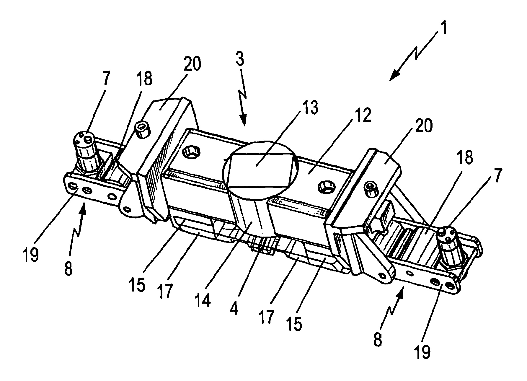
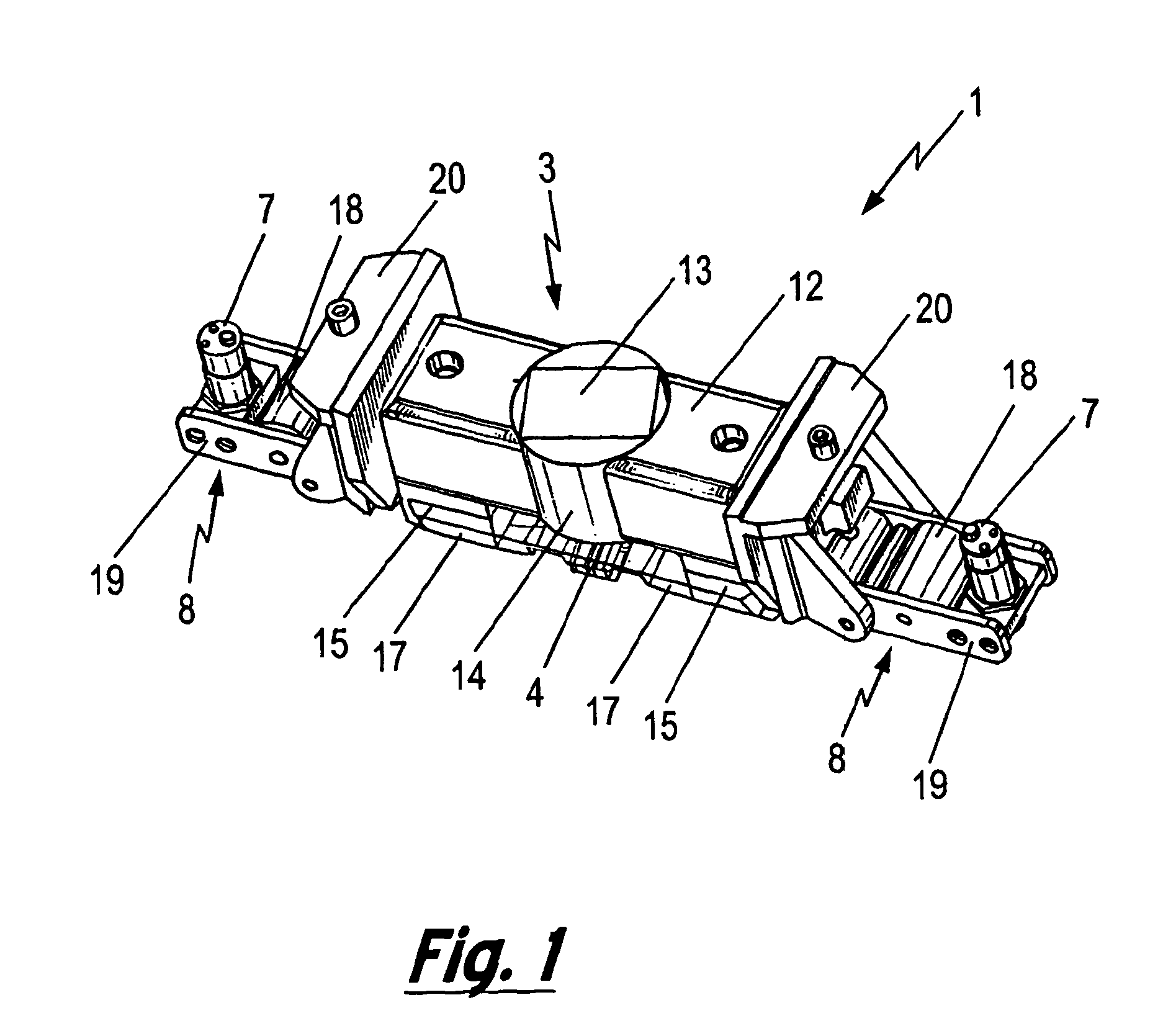
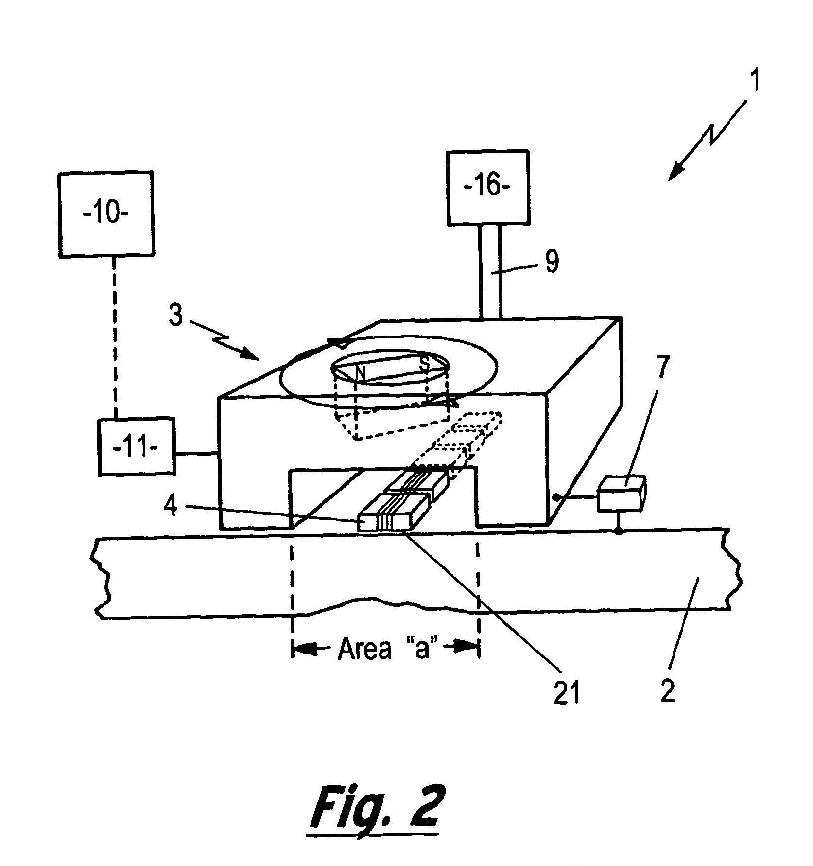
[0068]FIG. 1 presents a perspective view of a sensor module 1 in accordance with an embodiment of the invention while FIG. 2 presents a schematic representation of the sensor module 1 located with a component to be tested 2. The sensor module 1 can be seen to comprise a DC magnetiser unit 3, an array of eddy current probes 4, each eddy current probe 4 comprising an eddy current coil 5 with an integrated magnetic field sensor 6 e.g. a Hall sensor, one distance sensor 7 and two suspension wheel mechanisms 8. Electronic connectors 9 are employed to provide power to the sensor module 1 e.g. for the DC magnetiser unit 3, the eddy current coils 5, the Hall sensors 6 etc.

[0069]Signals detected by the sensor module 1 are transmitted to a data acquisition computer 10 that is employed to record all of the eddy current and Hall sensor data. The computer 10 may form an integrated part of the sensor module 1 or be located remotely. Transmission of the data may be via hardwiring e.g. via a fibre ...


PUM


Abstract

A method and apparatus for the inspection of electrically conductive components is described. The described apparatus comprises a sensor module having a magnetiser unit suitable for generating a variable DC magnetic field within the test component and an eddy current probe. The variable DC magnetic field and eddy current probe are configured to perform a partial saturation eddy current test upon the test component. The eddy current probe further comprises a magnetic field sensor that provides a means for measuring the permeability within the test component. Employing the magnetic field sensor provides apparatus that is more accurate and flexible in its modes of operation since such sensors provide a means for the actual permeability of a material being tested to be measured. The described methods and apparatus find particular application in the inspection of tubular components used in the oil and gas exploration and production industries.

Description

[0001]The present invention relates to non-destructive testing, and in particular to a method and apparatus for the inspection of electrically conductive components. Applications of the invention include the inspection of tubular components used in the oil and gas exploration and production industries.[0002]Non-destructive testing techniques are known for the detection and identification of defects and / or fatigue in the external wall of tubular components used in the oil and gas industry, such as casings, production tubing, and pipelines.[0003]One such non-destructive testing technique known in the art is eddy current testing (ECT). ECT is based on the principle of measuring the absolute or relative impedance Z of a probe or sensor that comprises a conducting coil to which an alternating current is applied. When the alternating current is applied to the probe a magnetic field develops in and around the coil. This magnetic field expands as the alternating current rises to a maximum a...

Claims


Application Information

Patent Timeline
Patent Type & Authority Applications(United States)
IPC IPC(8): G01R33/18
CPCG01N27/9033G01N27/82G01N27/9006G01B7/10G01B7/24G01B7/34G01N27/904G01N27/9053G01R33/1223
Inventor BOENISCH, ANDREAS
Owner SONOMATIC
Why Eureka
Try Eureka