Touch screen panel and image display device including same

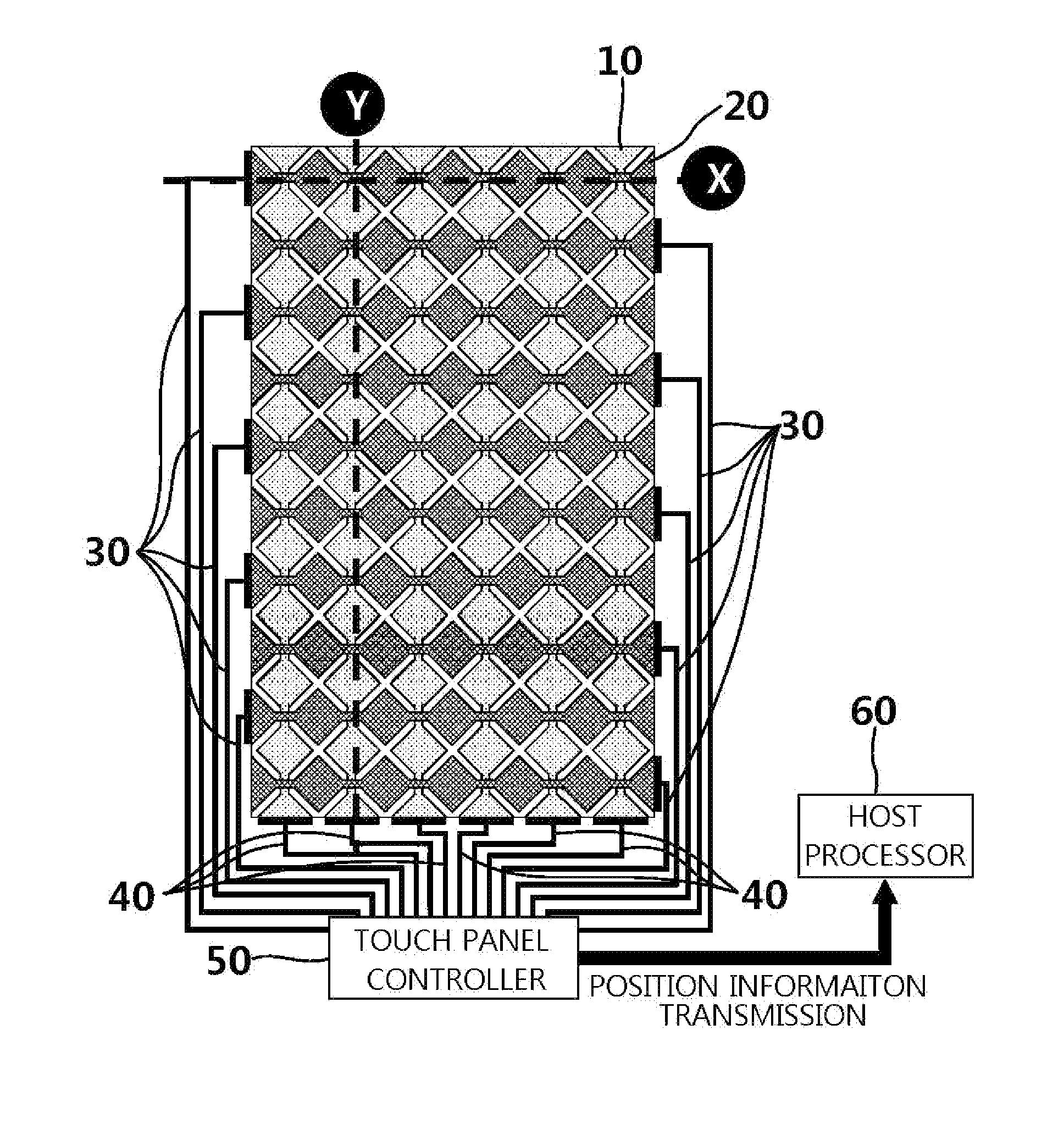
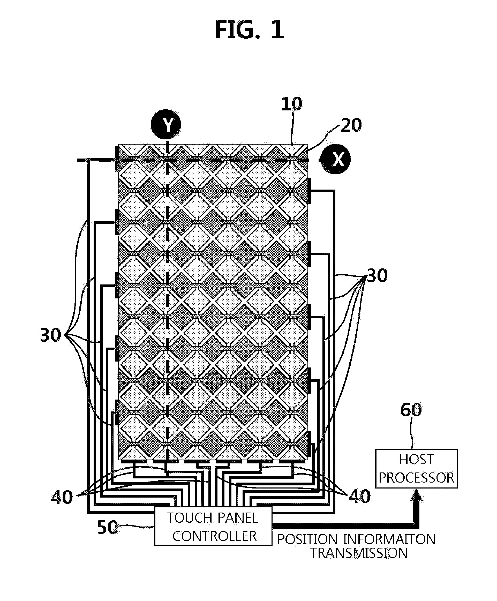
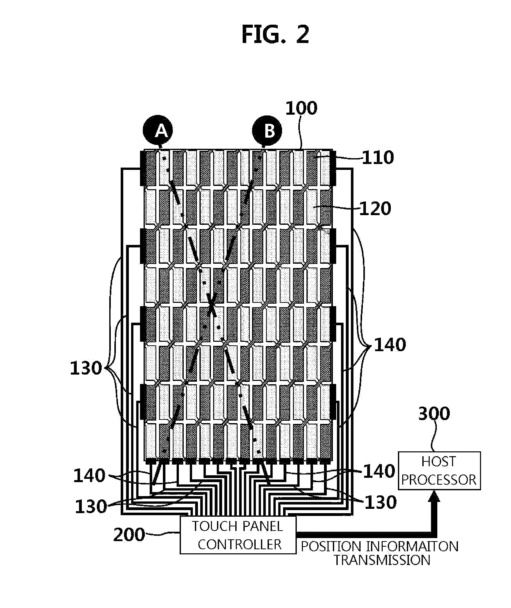
a technology of image display and touch screen, which is applied in the direction of electric digital data processing, instruments, computing, etc., can solve the problems of reducing affecting the use of the interface method, and affecting the use of the electronic device function, so as to reduce the number of sensing wires positioned, and reduce the width of the bezel

Inactive Publication Date: 2013-09-12
INTELLECTUAL DISCOVERY CO LTD
View PDF3 Cites 20 Cited by
  • Summary
  • Abstract
  • Description
  • Claims
  • Application Information

AI Technical Summary

Benefits of technology

[0031]According to the present invention, lateral sensing wire pattern lines in a diagonal direction having a predetermined angle which are different from a pattern in which horizontal and vertical-axis sensing wires cross each other are formed, thereby reducing the number of sensing wires positioned in a long axis of an image display device. As a result, according to the present invention, it is possible to

Problems solved by technology

However, this interface method has difficulties in using functions of electronic devices because the electronic devices are operated using restricted buttons.
For example, when there is no prior information about an operation method of input buttons when intuitively viewed by a user, it is difficult to input information to an electronic device.
However, since coordinates of the location are calculated through the physical contact, a device is liable to wear when the resistance film type touch screen panel is used for an extended period of time.
Since a surface of the resistance film type touch screen panel also uses a flexible plastic-based protective layer, the screen panel deteriorates in terms of durability due to scratches.
In addition, in the resistance film type touch screen panel, two touches or more may not be detected due to characteristics of a device driving method, and therefore implementation of multi-touch is impossible.
Compared to the resistance film type touch screen panel, the electrostatic capacitance type touch screen panel has a complex structure, high manufacturing costs,

Method used


Image

  • Touch screen panel and image display device including same
  • Touch screen panel and image display device including same
  • Touch screen panel and image display device including same

Examples


Embodiment Construction

[0048]Hereinafter, exemplary embodiments of the present invention will be described in detail. However, the present invention is not limited to the exemplary embodiments disclosed below, but can be implemented in various forms. The following exemplary embodiments are described in order to enable those of ordinary skill in the art to embody and practice the invention.

[0049]It will be understood that, although the terms first, second, etc. may be used herein to describe various elements, these elements should not be limited by these terms. These terms are only used to distinguish one element from another. For example, a first element could be termed a second element, and, similarly, a second element could be termed a first element, without departing from the scope of the present invention. As used here, the term “and / or” includes any and all combinations of one or more of the associated listed items.

[0050]It will be understood that when an element is referred to as being “connected” o...


PUM


Abstract

The present invention relates to a touch screen panel and to an image display device including same. The touch screen panel comprises: a first sensing wire pattern layer in which a plurality of first sensing wire pattern lines are formed in a first diagonal direction; a second sensing wire pattern layer in which a plurality of second sensing wire pattern lines are formed in a second diagonal direction so as to form a preset angle with the first sensing wires; and an insulation layer for providing insulation between the 1st sensing wire pattern layer and the 2nd sensing wire pattern layer. Since capacitive touch sensing wire pattern lines are disposed diagonally with a certain angle therebetween, the number of wires arranged on the major axis of the bezel of the touch screen panel can be reduced when compared to the resolution of touch screen panels of prior art in which the arrangement is perpendicular.

Description

TECHNICAL FIELD[0001]The present invention relates to a touch screen panel and an image display device including the same.BACKGROUND ART[0002]Inputs of existing electronic devices have been carried out in a method of performing selection, cancellation, and movement through simple button input. However, this interface method has difficulties in using functions of electronic devices because the electronic devices are operated using restricted buttons. For example, when there is no prior information about an operation method of input buttons when intuitively viewed by a user, it is difficult to input information to an electronic device.[0003]Accordingly, a touch screen panel that is operated by directly touching a screen for an input tool with an intuitive interface so as to reduce the discomfort of the user is very useful to enter information. The touch screen panel is categorized into a resistance film type touch screen panel that is obtained by vertically stacking two transparent co...

Claims


Application Information

Patent Timeline
IPC IPC(8): G06F3/041
CPCG06F3/044G06F2203/04111G06F3/041G06F3/0445G06F3/0446
Inventor KIM, TAE WHANHAN, GYU WANPARK, SU HYEONG
Owner INTELLECTUAL DISCOVERY CO LTD
Why Eureka
Try Eureka