Control device for electric rolling stock

a control device and electric rolling stock technology, applied in electric devices, brake systems, instruments, etc., can solve the problems of reducing the efficiency causing slip/skid, and re-inducing slip/skid, so as to improve the acceleration and deceleration performance of electric rolling stock, improve the accuracy, and reduce the calculation load

Active Publication Date: 2013-09-12
HITACHI LTD
View PDF1 Cites 10 Cited by
  • Summary
  • Abstract
  • Description
  • Claims
  • Application Information

AI Technical Summary

Benefits of technology

[0007]According to the present invention, even if the adhesion coefficient is drastically lessened, the slip/skid can be suppressed at a

Problems solved by technology

When a train car runs on ice, or gets outside with snow from a dried tunnel, an adhesion state between the train car and the rails drastically changes, and the adhesion coefficient is instantaneously lessened, resulting in occurrence of slip/

Method used


Image

  • Control device for electric rolling stock
  • Control device for electric rolling stock
  • Control device for electric rolling stock

Examples


first embodiment

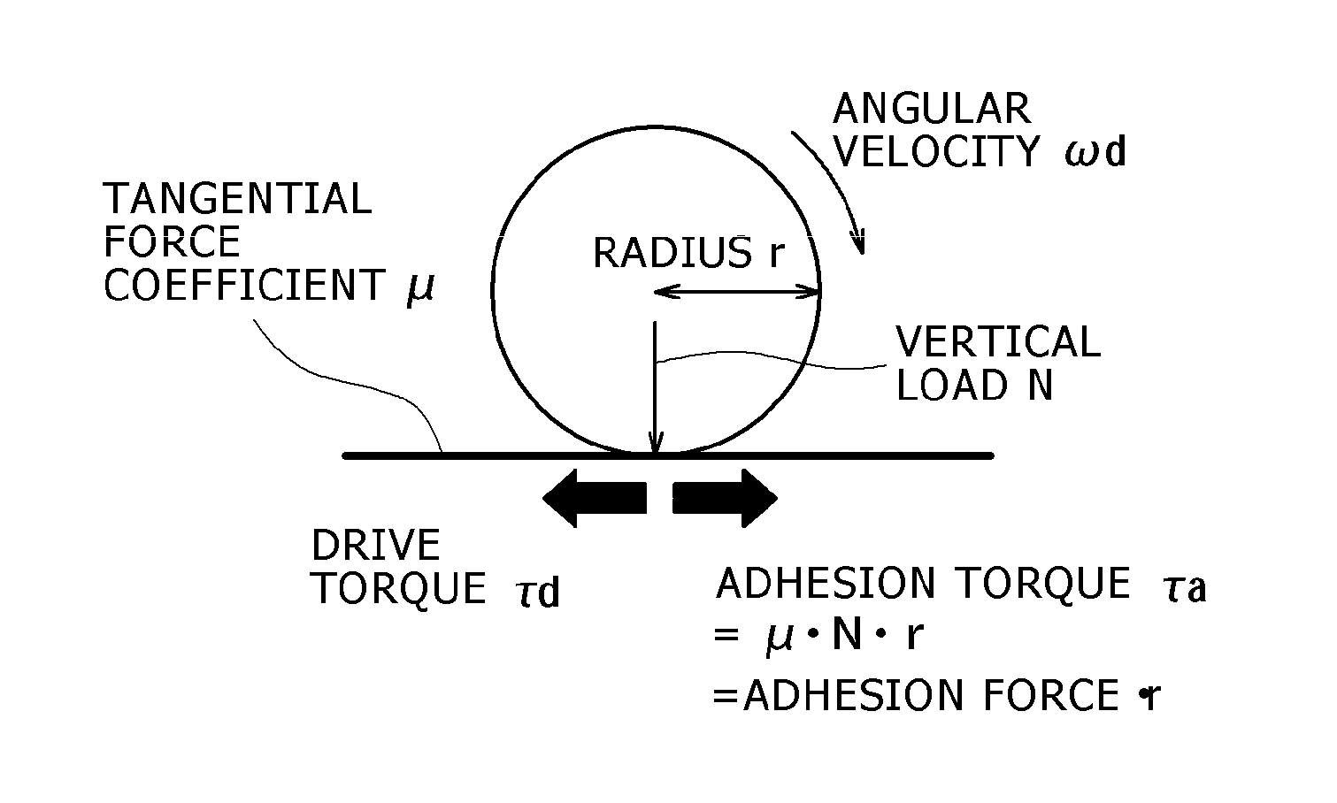
[0023]In this example, in an electric rolling stock control device mounted on an electric rolling stock 100 as illustrated in FIG. 10, a readhesion control of slip / skid is conducted so that whether the adhesion coefficient drastically drops, or not, is determined, and different controls are conducted according to the respective determination results. The electric rolling stock 100 includes wheels driven by an electric motor 200, an inverter 300 that controls the electric motor 200, and an inverter control unit 400 that controls the inverter 300. It is assumed that this embodiment is a part or one function of the inverter control unit 400. The electric rolling stock may be driven by an electric motor, and an electric power may be supplied from a cable, a storage battery, or the other driving sources.

[0024]FIG. 4 is a block diagram of a readhesion control according to this embodiment, which illustrates a part of a configuration of the inverter control unit 400. The readhesion control ...

second embodiment

[0053]In a second embodiment, a control flow from (001) to (004) in FIG. 8 illustrating the first embodiment is the same, and replaceable.

[0054]When a value of (τe_max−τe_slip) which is a difference between τe_max and τe_slip is larger than a given threshold value, or a value of (τe_max / τe_slip) which is a ratio of τe_max and τe_slip is larger than a given threshold value, the adhesion rapid drop detection unit 27 determines this condition as the rapid drop condition of the adhesion coefficient caused by a rapid change in the adhesion state, and outputs an adhesion rapid drop detection flag. When the adhesion rapid drop detection unit 27 detects the rapid drop of the adhesion coefficient, the torque suppression / return ratio calculation unit 28 outputs the torque suppression / return torque patterns on the basis of b1_large and b2_large[Nm] larger than b1 and b2[Nm] which are suppression / return differences under the normal condition. The b1 and b1_large may be set to coefficients for s...


PUM


Abstract

In order to minimize a calculation load and surely obtain a maximum adhesion torque, estimated adhesion torques are always stored, an maximum value is obtained from the stored plural estimated adhesion torques immediately before slip/skid is detected when detecting the slip/skid, and the maximum value is set as a maximum adhesion torque. The maximum adhesion torque immediately before the slip/skid is detected is compared with a value of the estimated adhesion torque when the slip/skid is detected. When the calculated value exceeds a threshold value, it is determined as a condition where an adhesion coefficient drastically drops, and a suppression/return ratio of the torque is switched to a lower value than that under a condition where the adhesion coefficient does not drastically drop. The value of the torque at the time of suppression or return is set to a smaller value to surely suppress the slip/skid.

Description

FIELD OF THE INVENTION[0001]The present invention relates to a technique for controlling slip / skip occurring between wheels of an electric rolling stock and rails.BACKGROUND OF THE INVENTION[0002]A control under which a driving or braking torque is suppressed and converged if wheels of a train Slip / skid, and the torque is returned to an original one if the slip / skid is converged is called “readhesion control”. There is the readhesion control using an adhesion torque which is a maximum value of the tangential force coefficient, and corresponds to an adhesion coefficient determined according to environmental conditions between the wheels and rails. The related art is disclosed in Japanese Unexamined Patent Application Publication No. Hei-1(1989)-243803. Regarding a value returning the torque, in the disclosure of this publication, “the adhesion coefficient is always calculated, and at the same time, a motor current corresponding to a torque generated in an electric motor, which is cal...

Claims


Application Information

Patent Timeline
IPC IPC(8): B61C15/12
CPCB60L3/106B60L15/20Y02T10/7275B60L2200/26B61C15/12Y02T10/72B60T8/1705B60L2240/423B60L2240/465B60T2210/124B60T2270/208Y02T10/64
Inventor WATANABE, ATSUSHISHIMADA, MOTOMIAONO, TOSHIHIROTACHIHARA, SHUICHI
Owner HITACHI LTD
Why Eureka
Try Eureka