Dual crankshaft engine

a crankshaft engine and crankshaft technology, applied in the direction of reciprocating piston engines, positive displacement engines, combustion engines, etc., can solve the problems of increasing the cost, weight, inertia, and friction of the engine, and the reaction torque imposed on the powertrain support structure (e.g., the engine mount) may be reduced, and the noise and vibration sensed inside the passenger compartment of the vehicle may be reduced.

Inactive Publication Date: 2013-09-19
FORD GLOBAL TECH LLC
View PDF11 Cites 22 Cited by
  • Summary
  • Abstract
  • Description
  • Claims
  • Application Information

AI Technical Summary

Benefits of technology

[0001]Dual counter-rotating crankshafts may be employed in an engine in order to cancel torque pulsations. For example, an engine including dual counter-rotating crankshafts may have a rigid coupling between the crankshafts, so that the acceleration of one crankshaft is counteracted by acceleration of the other crankshaft in the opposite rotational direction. Accordingly, reaction torque imposed upon a powertrain support structure (e.g., engine mounts) may be reduced, and correspondingly noise and vibration sensed inside a vehicle's passenger compartment may be reduced.

Problems solved by technology

However, the inventors herein have identified potential issues with such an approach.
As an example, since the vertically oriented cylinders of a four cylinder engine are paired and arranged in parallel, inertial forces acting on the reciprocating pistons cause an inherent unbalanced vibration that requires balance shafts to counteract the vibration in order for the engine to be mechanically balanced.
The addition of balance shafts to the engine increases cost, weight, inertia, and friction of the engine.
Moreover, the vertical orientation of the cylinders causes the height of the engine to be taller, which may be undesirable for engine fitting, vehicle styling, and raises the center of gravity of the engine, which may affect stability and control of a vehicle in which the engine is installed.

Method used


Image

  • Dual crankshaft engine
  • Dual crankshaft engine
  • Dual crankshaft engine

Examples


Embodiment Construction

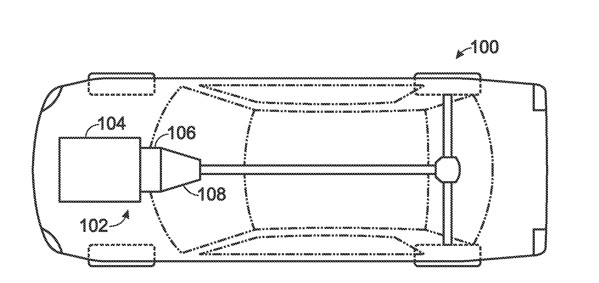
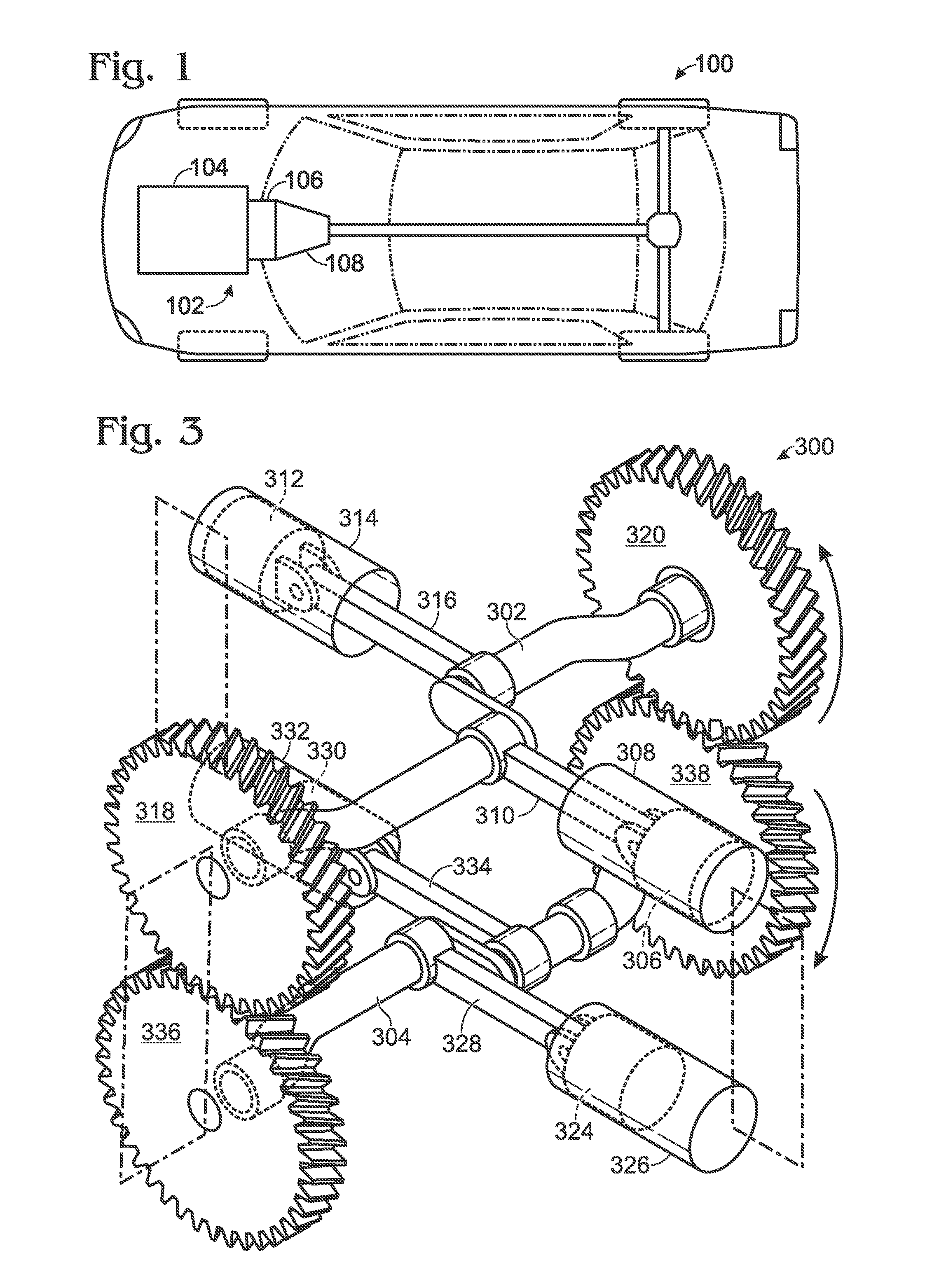
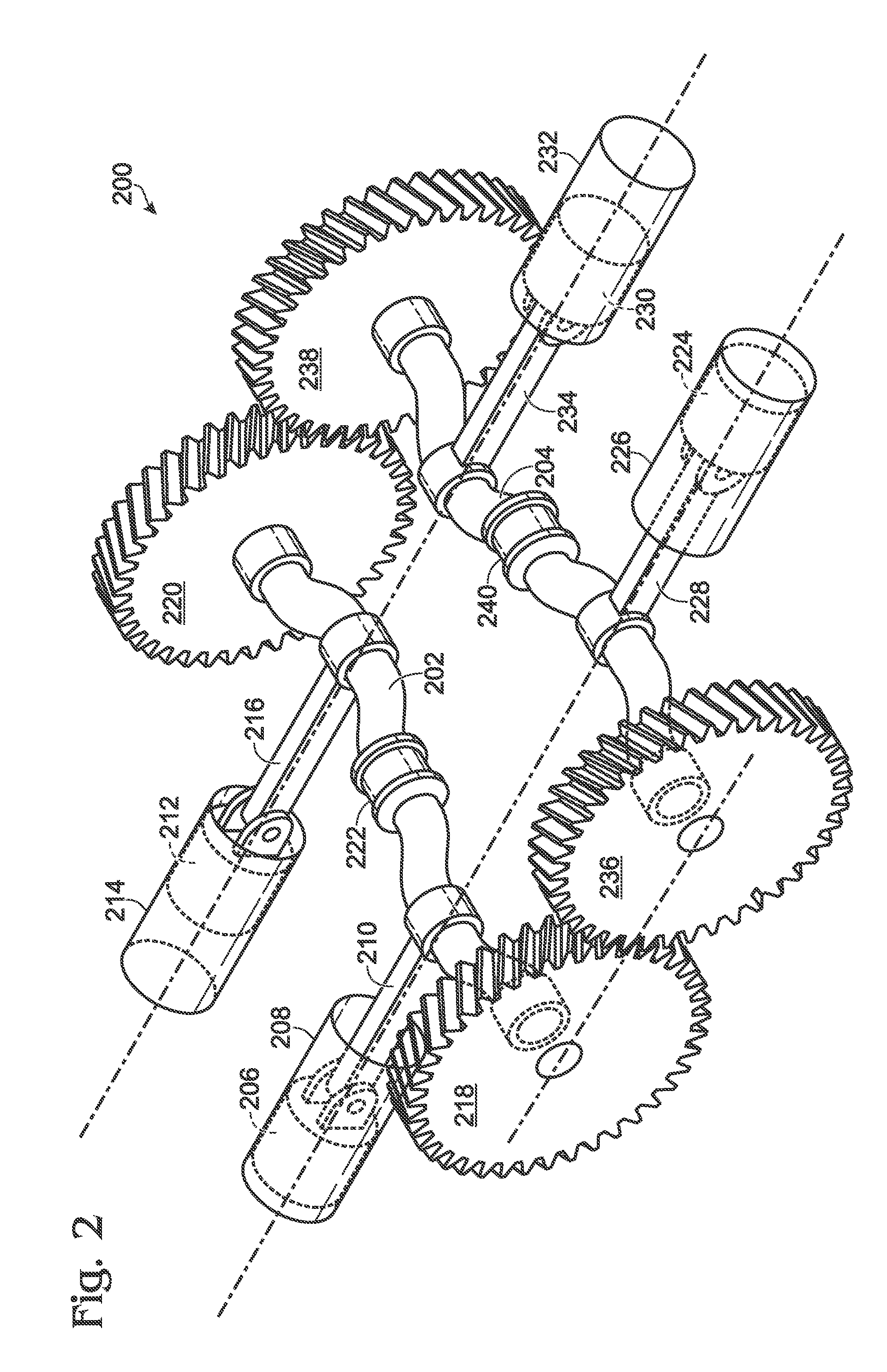
[0017]The present application describes various embodiments of a dual counter-rotating crankshaft engine that includes horizontally oriented and opposing cylinders in what may be referred to as a “boxer” engine configuration. The “boxer” concept may include modules of two cylinders that are located on opposite sides of an engine in approximately linear alignment with each other, The piston motions inside those opposing cylinders may be “minor images” of each other so that the forces of acceleration of the two pistons are equal and opposite and thereby cancel each other. When this pair of pistons is coupled to a single crankshaft, the associated connecting rods may be coupled one hundred eighty degrees opposite from each other; and therefore the two cylinders cannot be truly collinear with each other. The width of the connecting rods and the thickness of the crankshaft web that connects the two crankpins forces one cylinder to be installed farther forward than the other cylinder. The...


PUM


Abstract

A dual-crankshaft engine is presented. In one embodiment, the engine includes a first crankshaft and a second crankshaft. The second crankshaft is coupled with the first crankshaft such that the first crankshaft and the second crankshaft are horizontally coplanar. The engine further includes a first piston that is operable to reciprocate in a first horizontal cylinder via coupling with the first crankshaft, and a second piston that is operable to reciprocate in a second horizontal cylinder via coupling with the second crankshaft. The second horizontal cylinder is horizontally collinear with and opposing the first horizontal cylinder.

Description

BACKGROUND AND SUMMARY[0001]Dual counter-rotating crankshafts may be employed in an engine in order to cancel torque pulsations. For example, an engine including dual counter-rotating crankshafts may have a rigid coupling between the crankshafts, so that the acceleration of one crankshaft is counteracted by acceleration of the other crankshaft in the opposite rotational direction. Accordingly, reaction torque imposed upon a powertrain support structure (e.g., engine mounts) may be reduced, and correspondingly noise and vibration sensed inside a vehicle's passenger compartment may be reduced.[0002]One example of a dual counter-rotating crankshaft engine is provided by Berger et al. in U.S. Pat. No. 7,533,639. In this example, vertically oriented cylinders coupled to each crankshaft are paired and aligned in parallel. The dual counter-rotating crankshafts mutually cancel each other's vibrational torque reaction against the powertrain support structure, resulting in a reduced vibration...

Claims


Application Information

Patent Timeline
Patent Type & Authority Applications(United States)
IPC IPC(8): F02B75/28
CPCF16F15/24F02B75/243F02B75/065F01B1/10
Inventor LEONE, THOMAS G.BERGER, ALVIN HENRY
Owner FORD GLOBAL TECH LLC
Why Eureka
Try Eureka