Outlet mechanism with pulsatile splash

a technology of pulsatile and outlet mechanism, which is applied in the direction of spray nozzles, spray apparatuses, etc., can solve the problems of high manufacturing cost, high accuracy, and defectplurality, and achieve better left-and-right-swing effect, enhanced fluid flow ability, and better pulsatile splash outlet effect

Active Publication Date: 2013-09-19
XIAMEN SOLEX HIGH TECH IND CO LTD
View PDF8 Cites 13 Cited by
  • Summary
  • Abstract
  • Description
  • Claims
  • Application Information

AI Technical Summary

Benefits of technology

[0006]In a preferred embodiment, two vortex cavities (400) are arranged at the left side and the right side of the inlet waterway (100) to enhance the flowing ability of fluid.
[0021]5 the body and the attaching wall are fixed to form the main waterway with simple processing and low manufacturing cost.

Problems solved by technology

Because the mechanism achieves the outlet effect through the coupling of the outlet body and the movement assembly, a plurality of defects are present: 1 the structure is complicated with high space occupation, a lot of materials, high accuracy demanding and high manufacturing cost; 2 the movement part is easy to be abraded, and the outlet is unstable.

Method used


Image

  • Outlet mechanism with pulsatile splash
  • Outlet mechanism with pulsatile splash
  • Outlet mechanism with pulsatile splash

Examples


Embodiment Construction

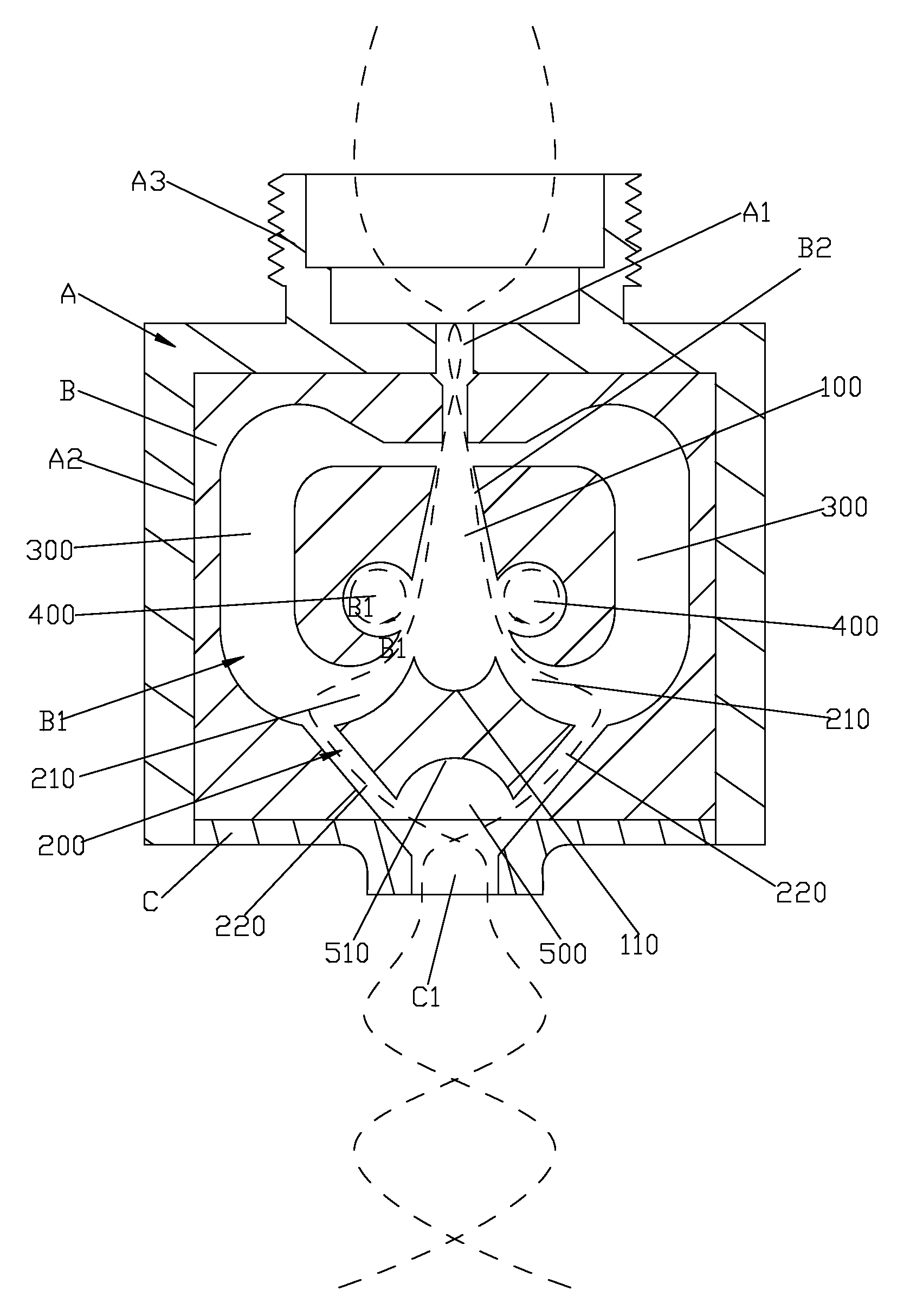
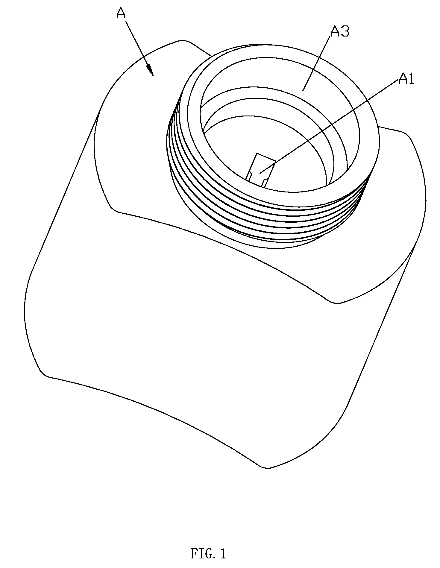
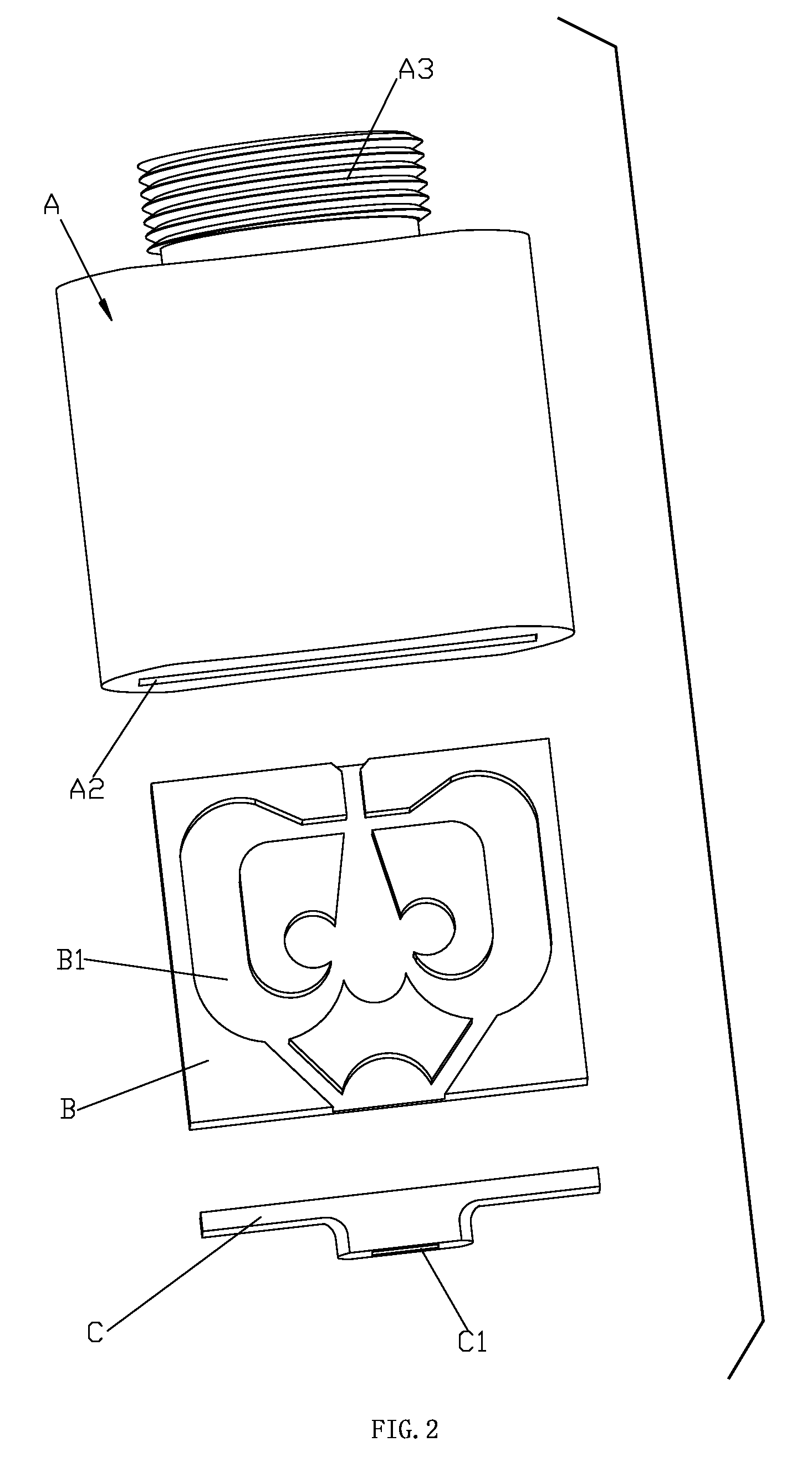
[0026]According to FIGS. 1, 2 and 3, an outlet mechanism with pulsatile splash comprises a body A, an attaching wall B and an outlet nozzle C. The body A and the attaching wall B are coupling with each other to form a main waterway.

[0027]The main waterway comprises an inlet waterway 100, two branch waterways 200 and two back-flow waterways 300; the two branch waterways 200 are communicating with the inlet waterway 100 and arranged symmetrically with respect to the inlet waterway 100, and the outlet directions of the outlet ends of the two branch waterways 200 are intersecting; the two back-flow waterways 300 are arranged symmetrically with respect to the inlet waterway 100, and one end of the back-flow waterway 300 is communicated with the branch waterway 200, another end of that is communicated with the inlet end of the inlet waterway 100.

[0028]In the present embodiment, the left side and the right side of the inlet waterway 100 are arranged to be inclined planes symmetrically, and...


PUM


Abstract

An outlet mechanism with pulsatile splash has a main waterway comprising an inlet waterway, two branch waterways and two back-flow waterways; the two branch waterways communicate with the outlet end of the inlet waterway and are arranged symmetrically with respect to the inlet waterway. The outlet directions of the outlet ends of the two branch waterways intersect; the two back-flow waterways are arranged symmetrically with respect to the inlet waterway, and one end of the back-flow waterway communicates with the branch waterway. Another end of that communicates with the inlet end of the inlet waterway. Part of water in the branch waterway is returned to the inlet end of the inlet waterway by the back-flow waterway. The remain water in the two branch waterways intersect when water comes out of the outlet, so that the left-and-right-swing outlet effect, and then the pulsatile splash outlet effect are generated.

Description

FIELD OF THE INVENTION[0001]The present invention relates to an outlet mechanism with pulsatile splash.BACKGROUND OF THE INVENTION[0002]The outlet mechanism with pulsatile splash at the prior art, comprises an outlet body and a movement assembly that is arranged in the outlet body in a moving manner, the left-and-right-swing outlet effect is generated from the outlet body through the relative movement of the movement assembly to the outlet body, and then the pulsatile splash outlet effect is generated. Because the mechanism achieves the outlet effect through the coupling of the outlet body and the movement assembly, a plurality of defects are present: 1 the structure is complicated with high space occupation, a lot of materials, high accuracy demanding and high manufacturing cost; 2 the movement part is easy to be abraded, and the outlet is unstable.SUMMARY OF THE INVENTION[0003]The object of the present invention is to offer an outlet mechanism with pulsatile splash which overcomes...

Claims


Application Information

Patent Timeline
Patent Type & Authority Applications(United States)
IPC IPC(8): B05B1/08
CPCB05B1/08
Inventor ZHOU, HUASONGJIANG, LIYANG, YURONGZOU, XIANGUO
Owner XIAMEN SOLEX HIGH TECH IND CO LTD
Why Eureka
Try Eureka