RFID tag system and RFID reader/writer
- Summary
- Abstract
- Description
- Claims
- Application Information
AI Technical Summary
Benefits of technology
Problems solved by technology
Method used
Image

Examples
first embodiment
(1) First Embodiment
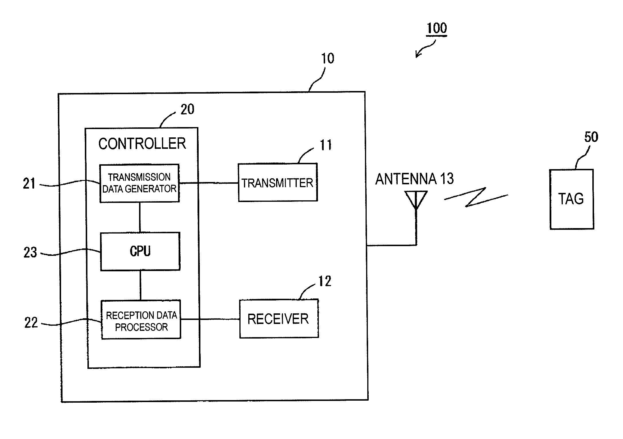
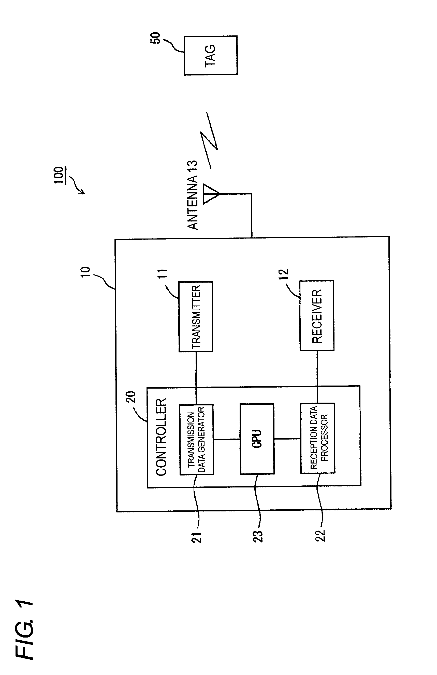
[0026]Hereinafter, an embodiment of the present invention will be described with reference to the drawings. FIG. 1 is a schematic block diagram illustrating an entire configuration of an RFID tag system 100 according to an embodiment of the present invention. The RFID tag system 100 includes an RFID reader / writer 10 and an RFID tag 50. The RFID reader / writer 10 includes a controller 20 that controls the whole of the RFID reader / writer 10, a transmitter 11 and a receiver 12, which are connected to the controller 20, and an antenna 13 that is connected to the transmitter 11 and the receiver 12.
[0027]The controller 20 includes a CPU 23 that controls the controller 20, a transmission data generator 21 that is controlled by the CPU 23 to generate such predetermined transmission data as a command, and a receiving data processor 22 that processes received data received from the RFID tag 50. The data generated by the transmission data generator 21 is transmitted to the R...
second embodiment
(2) Second Embodiment
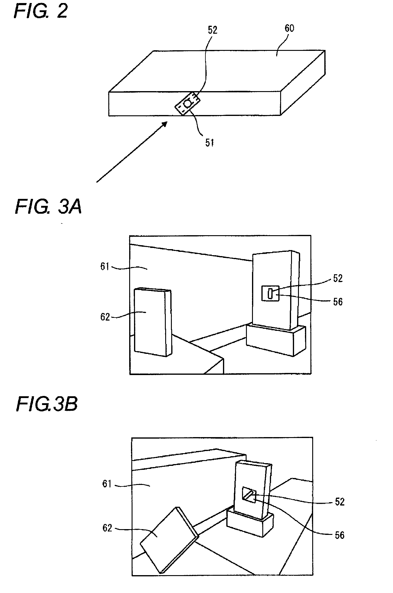
[0039]A second embodiment of the present invention will be described below. In the conventional embodiment, as illustrated in FIG. 5A, the RFID tag 51 including a horizontally extending antenna 52a is horizontally provided in a rectangular tag case 53a including a pair of horizontal side facing each other and a pair of vertical sides facing each other (see FIG. 5A).
[0040]On the other hand, in the second embodiment, the antenna of the RFID tag 54 is obliquely disposed by around 45 degrees with respect to a reflecting surface (the floor or the wall). Such a structure as the floor and the wall is horizontal or vertical to the ground surface, and the structure is rarely obliquely disposed. That is, usually the reflection point is horizontal or vertical to the ground surface. Because the RFID tag is placed on the pallet, frequently the RFID tag is used in the horizontal or vertical state.
[0041]Accordingly, in the case that the antenna of the RFID tag is obliquely pla...
third embodiment
(3) Third Embodiment
[0047]A third embodiment of the present invention will be described below. In the case that the pallet is used while the RFID tag is attached to the pallet, the pallet is placed in not only the horizontal direction but also the vertical direction. When the RFID tag is obliquely attached to the pallet by correct 45 degrees, the RFID tag can deal with both the horizontally-placed pallet and the vertically-placed pallet. However, actually the RFID tag is not always obliquely attached to the pallet by correct 45 degrees. In this case, in the first and second embodiments, a communication failure is generated, and the RFID tag cannot deal with both the horizontally-placed pallet and the vertically-placed pallet only when the slant polarization is used. For example, in the case that the RFID tag is placed at obliquely right 45 degrees while the pallet is horizontally placed, the RFID tag becomes obliquely left 45 degrees when the pallet is placed upright. In the case th...
PUM
 Abstract
Description
Claims
Application Information
 - R&D
- Intellectual Property
- Life Sciences
- Materials
- Tech Scout
- Unparalleled Data Quality
- Higher Quality Content
- 60% Fewer Hallucinations
Browse by: Latest US Patents, China's latest patents, Technical Efficacy Thesaurus, Application Domain, Technology Topic, Popular Technical Reports.
© 2025 PatSnap. All rights reserved.Legal|Privacy policy|Modern Slavery Act Transparency Statement|Sitemap|About US| Contact US: help@patsnap.com