Anatomical location markers and methods of use in positioning sheet-like materials during surgery

a technology of anatomical location markers and positioning sheets, applied in the field of orthopedic medicine and surgery, can solve the problems of complex mechanical properties of the rotator cuff muscles, damage to the rotator cuff or the rotator cuff tendons, and damage to the rotator cuff, etc., to achieve accurate positioning and delivery.

Active Publication Date: 2013-09-19
ROTATION MEDICAL
View PDF38 Cites 61 Cited by
  • Summary
  • Abstract
  • Description
  • Claims
  • Application Information

AI Technical Summary

Benefits of technology

[0016]The markers of the present disclosure can be used with an implant delivery system for accurately positioning and deploying or delivering a sheet-like implant. One embodiment provides an implant delivery system including an implant retainer assembly and an implant spreader assembly. The implant retainer assembly and the implant spreader assembly are provided proximate the distal end of a delivery shaft. The implant retainer assembly is configured to releasably couple a sheet-like implant thereto for positioning the sheet-like implant at a treatment site. The implant spreader assembly is configured to expand the sheet-like implant so that the sheet-like implant covers the treatment site.
[0022]In some exemplary embodiments, a sheath is disposed about the implant spreader assembly. The sheath is slidable in a direction generally parallel to a longitudinal axis of the delivery shaft such that the sheath can be retracted proximally from around the implant spreader assembly. The sheath can include a bullet nose distal end to ease insertion into the shoulder space.

Problems solved by technology

The mechanics of the rotator cuff muscles are complex.
With its complexity, range of motion and extensive use, a common soft tissue injury is damage to the rotator cuff or rotator cuff tendons.
Damage to the rotator cuff is a potentially serious medical condition that may occur during hyperextension, from an acute traumatic tear or from overuse of the joint.
A tear at the insertion site of the tendon with the humerus, may result in the detachment of the tendon from the bone.
Additionally, the strain or tear can occur within the tendon itself.
The placement of the patch can be accomplished readily in an open surgical procedure, however, placement and attachment of the patch in an arthroscopic procedure has been shown to be very difficult.
In many instances, the shoulder does not heal, and the partial thickness tear can be the source of chronic pain and stiffness.
Further, the pain and stiffness may cause restricted use of the limb which tends to result in further degeneration or atrophy in the shoulder.
Surgical intervention may be required for a partial thickness tear of less than 50%, however, current treatment interventions do not include repair of the tendon, and rather the surgical procedure is directed to arthroscopic removal of bone to relieve points of impingement or create a larger tunnel between the tendon and bone that is believed to be causing tendon damage.
This may result in less use of the arm and shoulder which causes further degeneration of the tendon and may lead to more extensive damage.
This procedure requires extensive rehabilitation, has relatively high failure rates and subjects the patient who first presented and was treated with a partial thickness tear less than 50% to a second surgical procedure.
It has been shown to be very difficult to properly position and attach a sheet-like implant unless the treatment site is accessed in an open procedure.
Further, adequate procedures do not exist for repairing a partial thickness tear of less than 50% in the supraspinatus tendon.
Current procedures attempt to alleviate impingement or make room for movement of the tendon to prevent further damage and relieve discomfort but do not repair or strengthen the tendon.
Use of the still damaged tendon can lead to further damage or injury.
Prior damage may result in degeneration that requires a second more drastic procedure to repair the tendon.
Further, if the prior procedure was only partially successful in relieving pain and discomfort, a response may be to use the shoulder less which leads to degeneration and increased likelihood of further injury along with the need for more drastic surgery.

Method used


Image

  • Anatomical location markers and methods of use in positioning sheet-like materials during surgery
  • Anatomical location markers and methods of use in positioning sheet-like materials during surgery
  • Anatomical location markers and methods of use in positioning sheet-like materials during surgery

Examples


Embodiment Construction

[0061]The following detailed description should be read with reference to the drawings in which similar elements in different drawings are numbered the same. The drawings, which are not necessarily to scale, depict illustrative embodiments and are not intended to limit the scope of the invention.

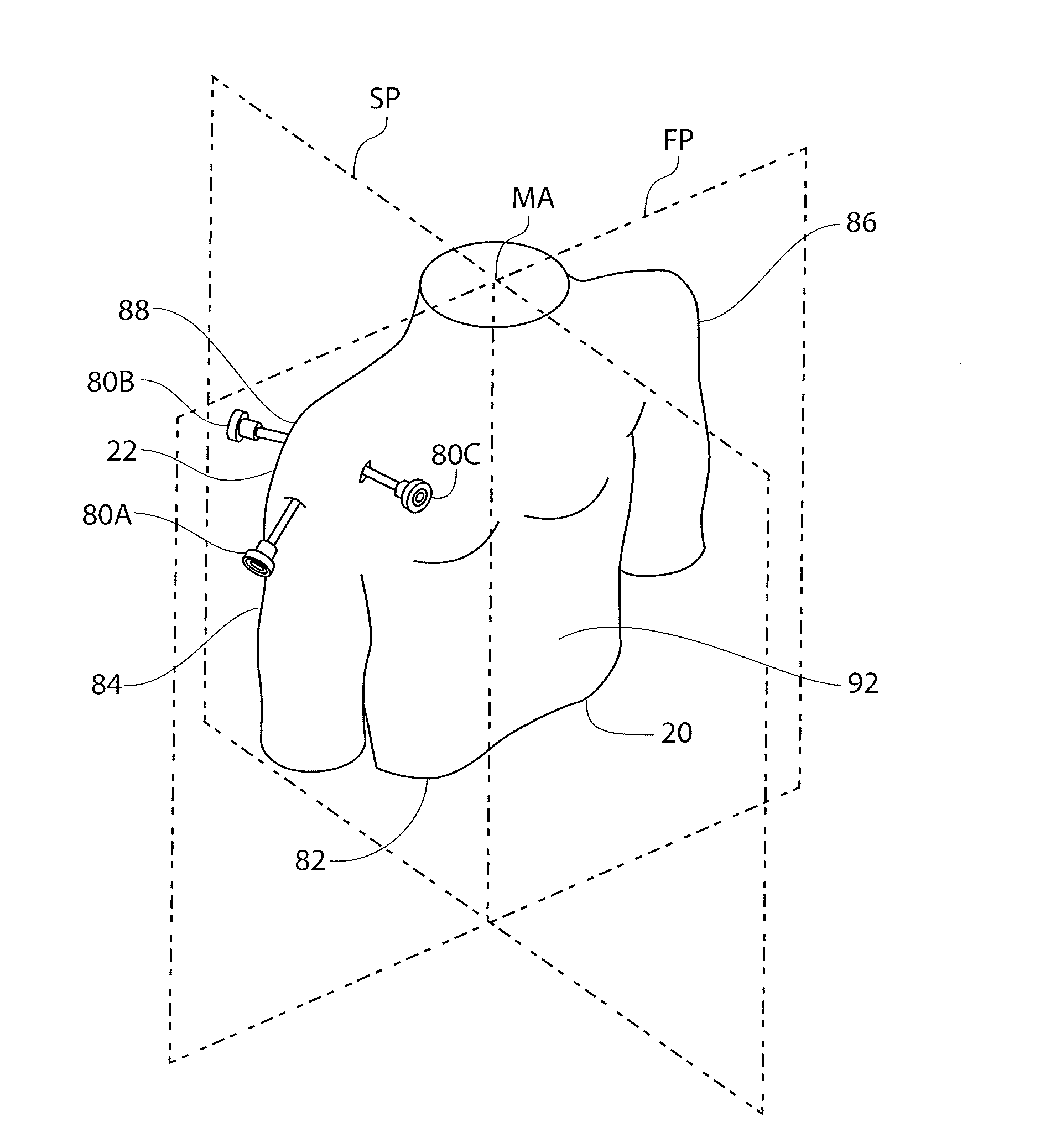
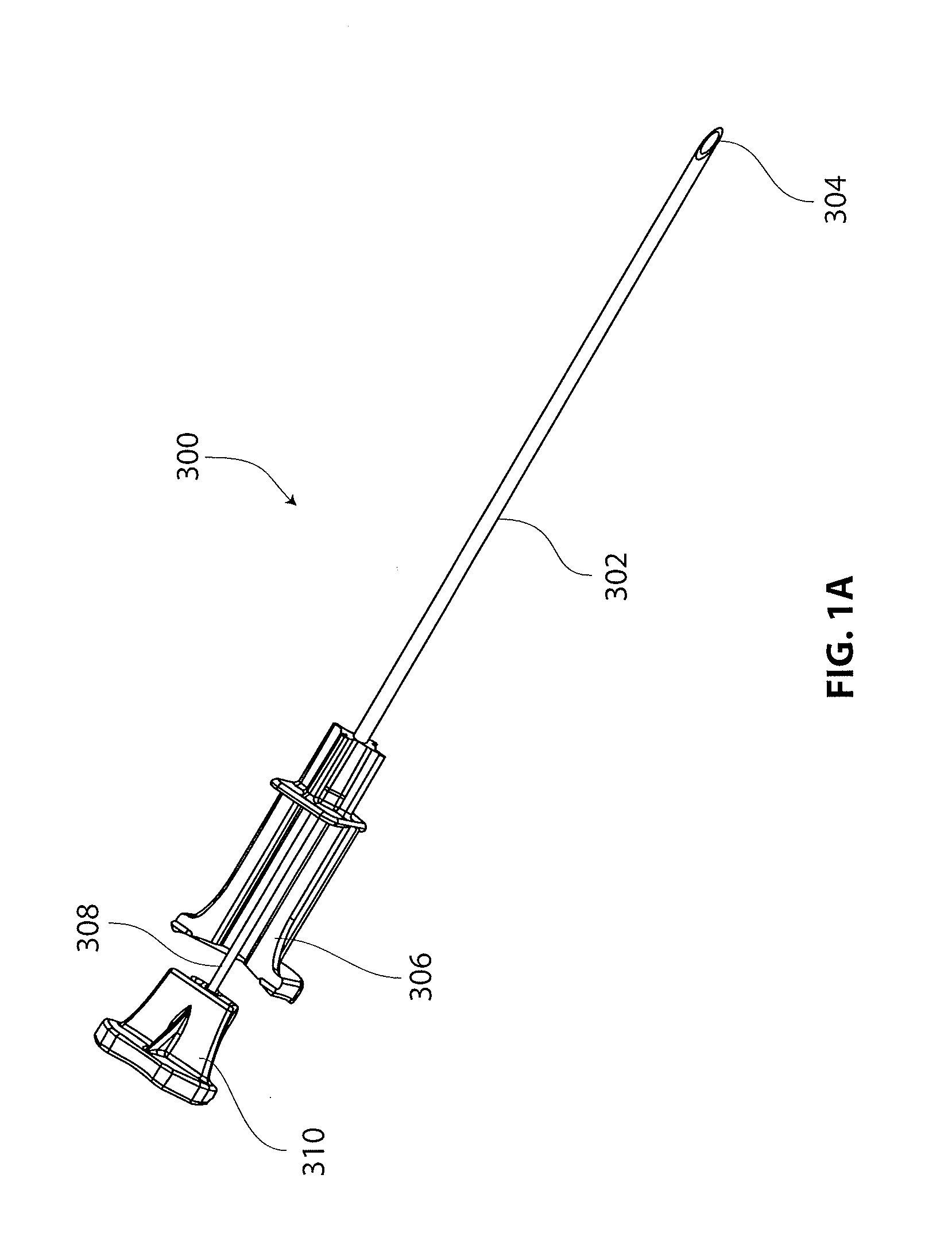
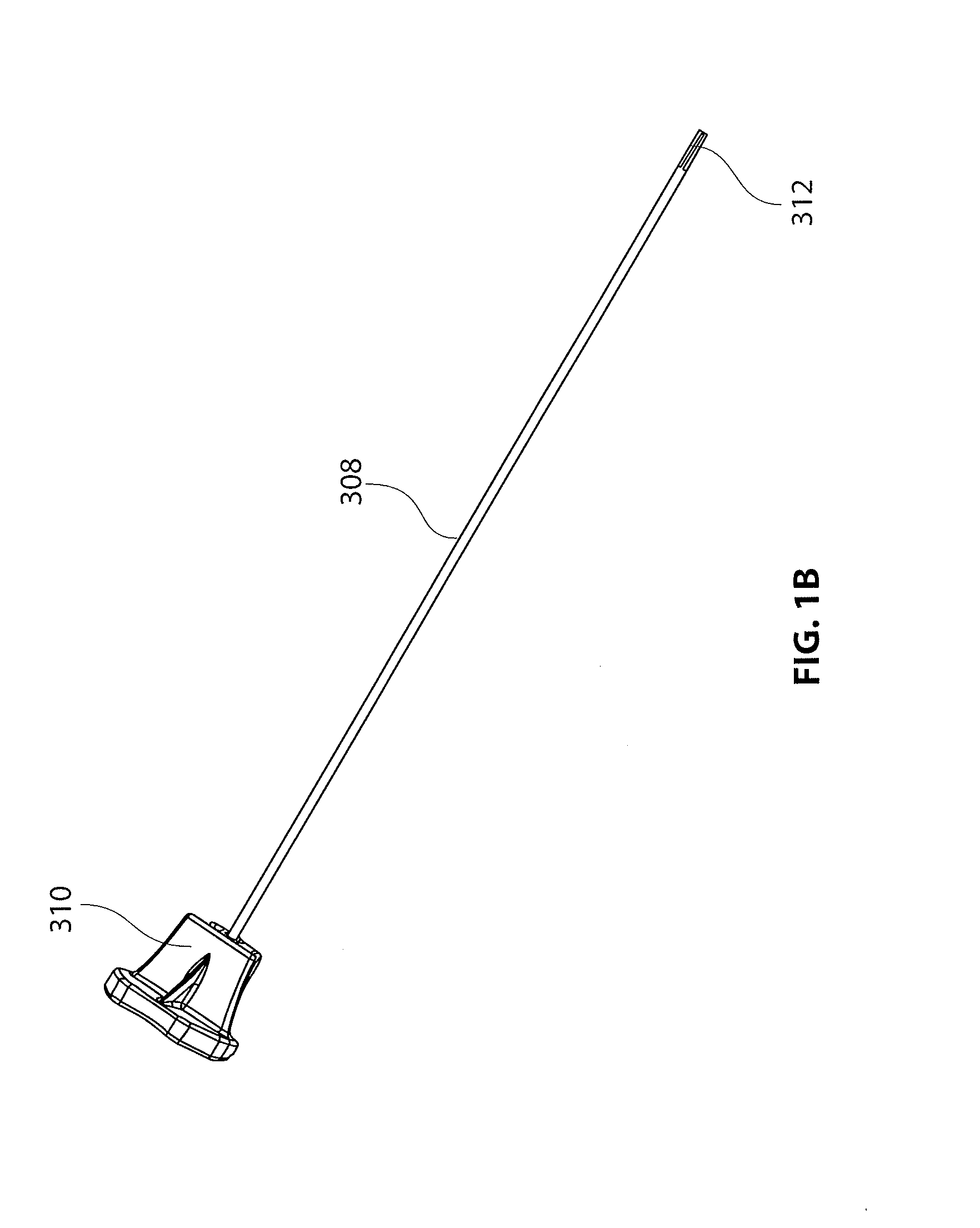
[0062]The present disclosure is directed to a tissue marker assembly that is particularly useful with an implant delivery system for accurately positioning and deploying or delivering a sheet-like implant to a treatment site. The tissue marker assembly and delivery system are discussed in detail with respect to treatment of tendons in articulating joints, specifically the supraspinatus tendon of the rotator cuff in the shoulder. However, it is recognized that the tissue marker assembly, delivery system and other components of a kit disclosed herein can be utilized in any areas of the body wherein it is desired to identify and mark an anatomical location. With the tissue marked, devices and m...


PUM


Abstract

A tissue marker assembly which can be useful with an implant delivery system for delivering a sheet-like implant is disclosed. The tissue marker assembly can include a delivery sleeve with a tissue marker slidably disposed within a lumen therethrough. A proximal handle can be coupled to the tissue marker and delivery sleeve, having a first part and a second part. The second part of the proximal handle can be releasably attached to the tissue marker proximal end so that the second part can be removed to allow the delivery sleeve to be removed proximally over the tissue marker after it is affixed to tissue. The distal portion of the marker can include a plurality of longitudinally extending arms when unconstrained project outward from the shaft to retain the marker's position in tissue.

Description

CROSS REFERENCE TO RELATED APPLICATIONS[0001]This application is a continuation of U.S. application Ser. No. 13 / 722,940 filed on Dec. 20, 2012, entitled “ANATOMICAL LOCATION MARKERS AND METHODS OF USE IN POSITIONING SHEET-LIKE MATERIALS DURING SURGERY”, which claims priority to U.S. Provisional Application No. 61 / 581,631 filed on Dec. 29, 2011, the disclosure of each of which are incorporated by reference herein in their entirety.[0002]The present disclosure is related to the following commonly assigned co-pending applications, the disclosures of which are incorporated herein by reference: U.S. Application No. 61 / 443,169 filed on Feb. 15, 2011; and U.S. Provisional Application No. 61 / 581,628 Attorney Docket No. 10322-715.100, entitled, “METHODS AND APPARATUS FOR DELIVERING AND POSITIONING SHEET-LIKE MATERIALS IN SURGERY,” filed on Dec. 29, 2011 and U.S. Provisional Application No. 61 / 581,629 Attorney Docket No. 10322-716.100, entitled, “GUIDEWIRE HAVING A DISTAL FIXATION MEMBER FOR ...

Claims


Application Information

Patent Timeline
Patent Type & Authority Applications(United States)
IPC IPC(8): A61B19/00A61B17/88
CPCA61B17/88A61B2017/0046A61B2017/00867A61B19/54A61B2017/22047A61B2019/5408A61B2019/5491A61B2017/22044A61B90/39A61B2090/3908A61B2090/3991
Inventor EUTENEUER, CHARLES L.ZENZ-OLSON, NATHANIEL Z.QUACKENBUSH, JOHNSIMS, JEFFVAN KAMPEN, CRAIG
Owner ROTATION MEDICAL
Why Eureka
Try Eureka