Electro-hydraulic pilot operated relief valve

a technology of electric motor and relief valve, which is applied in the direction of valve operating means/releasing devices, mechanical equipment, transportation and packaging, etc., can solve the problems of unsatisfactory, unfavorable, and unnecessary heat in hydraulic fluid, and achieve the effect of reducing the pressure needed to open the valve and adding cost and complexity

Active Publication Date: 2013-09-26
PARKER INTANGIBLES LLC
View PDF1 Cites 7 Cited by
  • Summary
  • Abstract
  • Description
  • Claims
  • Application Information

AI Technical Summary

Benefits of technology

[0011]Further, a design that utilizes an additional relief valve set to a minimal pressure in combination with a pilot operated check valve to allow the excess fluid to return to tank addresses the issues of heat and energy, it adds cost and complexity by adding additional valves to the hydraulic circuit as well as causes internal leakage issues inherent to the design.
[0012]The design of the present application works to address the issues listed above. By pilot operating the extend relief valve, the low pressure return of fluid can still be accomplished without the need to incorporate an additional valve into the hydraulic circuit. Utilizing a spool valve to pilot operate the extend relief valve during the retract function, the larger area of the spool can be used to open the valve as opposed the small area of the valve thereby reducing the pressure necessary to open the valve. This essentially turns a high pressure relief valve during extend into a low pressure return valve during retract.

Problems solved by technology

Because use of a retract relief valve to dump this excess fluid to tank results in this fluid being dumped at excessively high pressures—thus creating unnecessary heat in the hydraulic fluid and wasting energy—it is not desirable.
Further, a design that utilizes an additional relief valve set to a minimal pressure in combination with a pilot operated check valve to allow the excess fluid to return to tank addresses the issues of heat and energy, it adds cost and complexity by adding additional valves to the hydraulic circuit as well as causes internal leakage issues inherent to the design.

Method used


Image

  • Electro-hydraulic pilot operated relief valve
  • Electro-hydraulic pilot operated relief valve
  • Electro-hydraulic pilot operated relief valve

Examples


Embodiment Construction

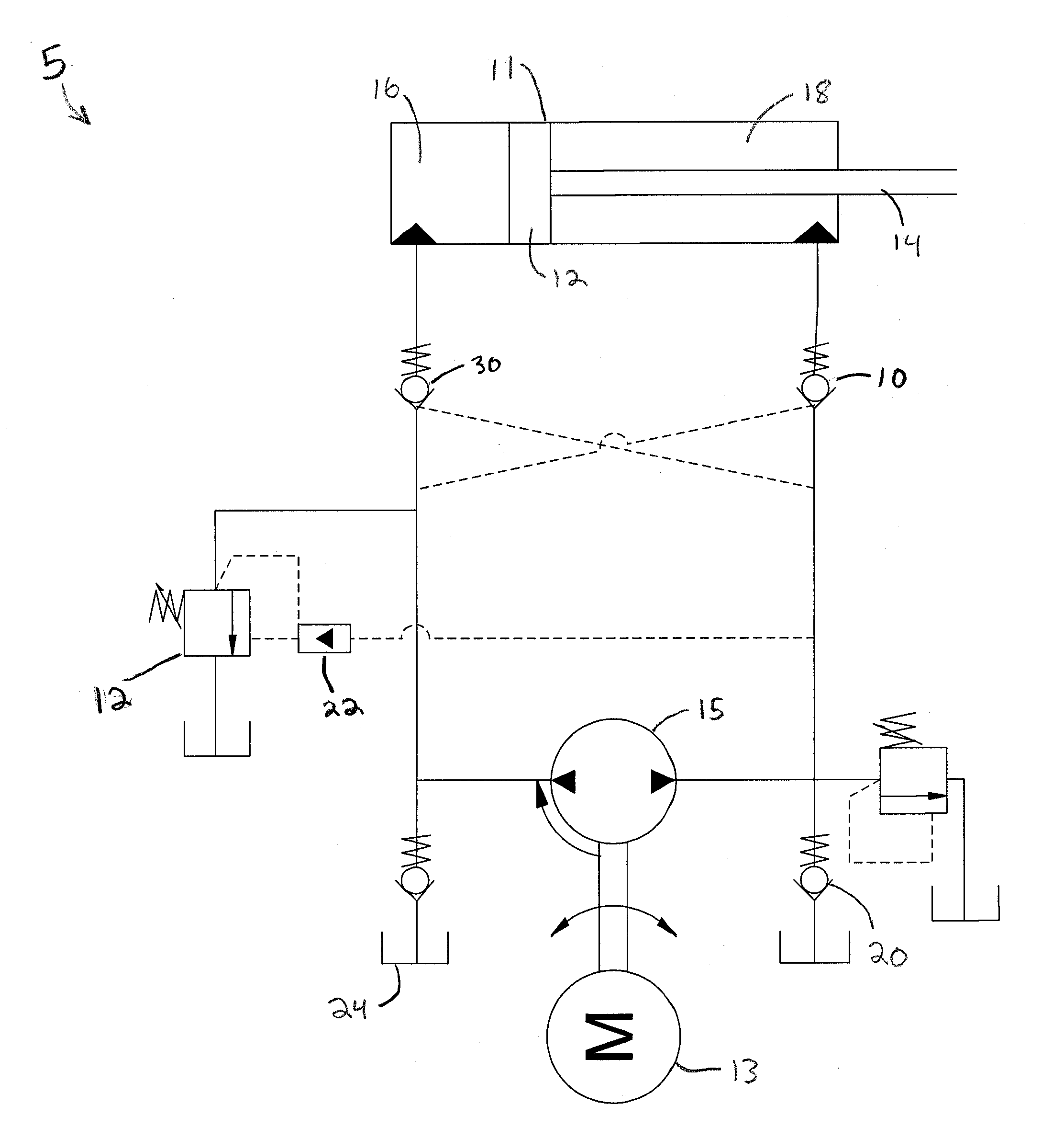
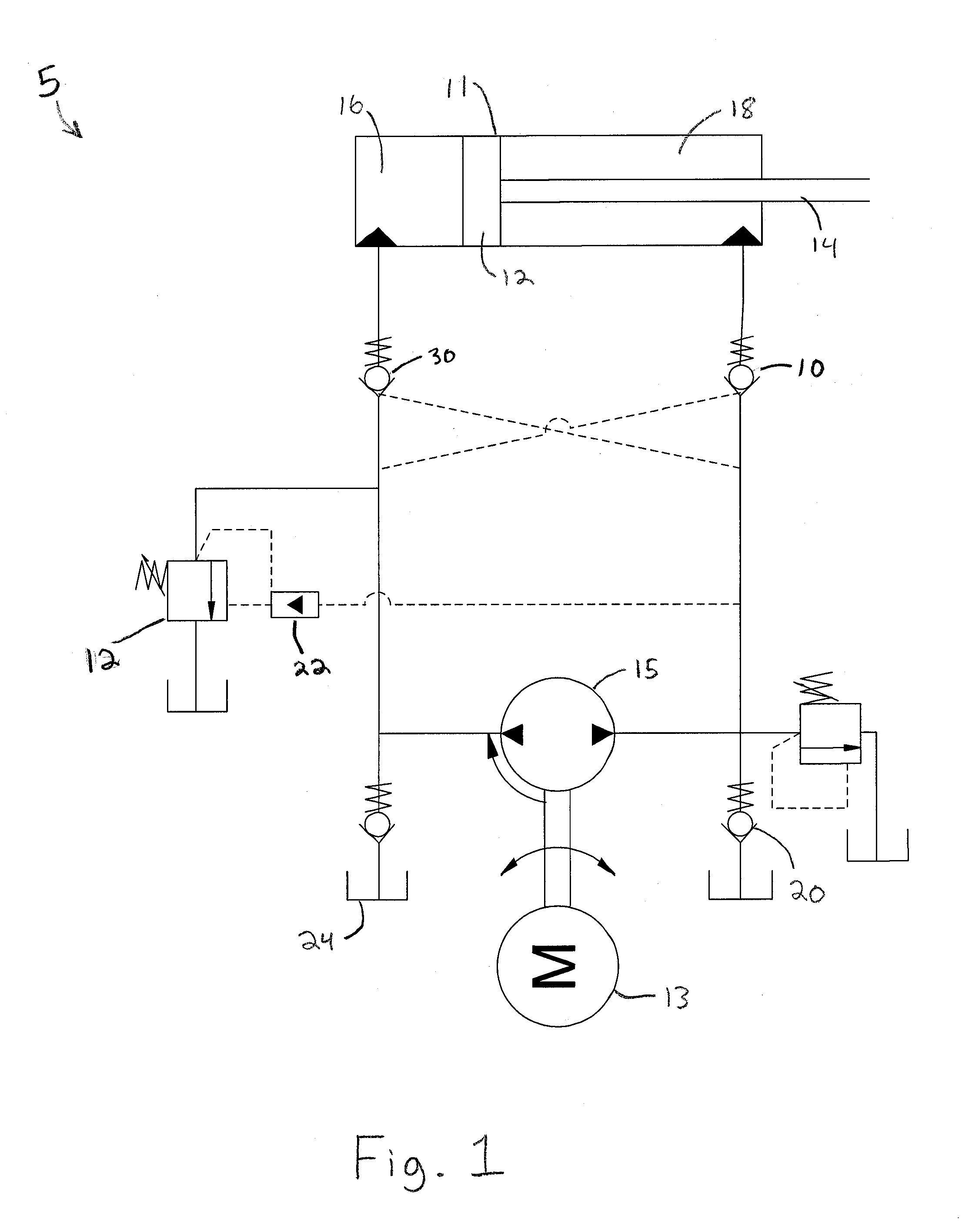
[0038]An exemplary method of dumping excess fluid during retraction of a cylinder 11 actuator includes pumping fluid with a pump 15 from a piston side 16 of the cylinder to a rod side 18 of the cylinder; opening a first check valve with relatively high pressure fluid from a downstream side of the pump 15 to allow flow into the rod side 18 of the cylinder 11; and opening an extend relief valve via a first spool with fluid from the downstream side of the pump to allow excess fluid at an upstream side of the pump 15 to return to a reservoir 24 at relatively low pressure.

[0039]The method may further include opening a second check valve via a second spool with relatively high pressure fluid from the downstream side of the pump to allow flow from the piston side of the cylinder.

[0040]Referring initially to FIG. 1, shown is an exemplary cylinder actuator circuit 5 including a cylinder 11 a motor 13 and a pump 15. The cylinder actuator 11 includes a piston 6 and a rod 14 defining a piston s...


PUM


Abstract

Provided is a method of and valve assembly for dumping excess fluid during retraction of a cylinder actuator. The method includes pumping fluid with a pump from a piston side of the cylinder to a rod side of the cylinder; opening a first check valve with relatively high pressure fluid from a downstream side of the pump to allow flow into the rod side of the cylinder; and opening an extend relief valve via a first spool with fluid from the downstream side of the pump to allow excess fluid at an upstream side of the pump to return to a reservoir at relatively low pressure.

Description

RELATED APPLICATIONS[0001]This application claims the benefit of U.S. Provisional Application No. 61 / 613,293 filed Mar. 20, 2012, which is hereby incorporated herein by reference.FIELD OF INVENTION[0002]The present invention relates generally to hydraulic valves, and more particularly to a pilot-operated relief valve.BACKGROUND[0003]Cylinder actuators are used to actuate loads. The cylinder may impart a force while either extending or retracting which in turn moves the load respectively. This operation can be performed with several different styles of actuators including electro-mechanical, pneumatic, and hydraulic. Various valves control the fluid circuits in hydraulic systems.[0004]An electro-hydraulic actuator (EHA), for example, functions in a bi-rotational design; the direction of the electric motor rotation and thus hydraulic pump flow is determined by the electric polarity applied to the motor leads. Thus when the polarity is applied in the extend direction, the pump will pro...

Claims


Application Information

Patent Timeline
Patent Type & Authority Applications(United States)
IPC IPC(8): F15B13/02
CPCF15B13/024F15B7/006F15B2211/20538F15B2211/785F15B2211/30515F15B2211/50518F15B2211/7053F15B2211/20561F15B13/015Y10T137/86485
Inventor OLSON, MATTHEW
Owner PARKER INTANGIBLES LLC
Why Eureka
Try Eureka