
Electrical switch arrangement

a switch arrangement and switch technology, applied in the direction of contact driving mechanism, electrical apparatus, contact mechanism, etc., can solve the problems of large structural height and extremely limited installation space, and achieve the effect of reducing and reducing the height of the structural height of the switch arrangemen

Active Publication Date: 2013-09-26
JOHNSON ELECTRIC SA
View PDF5 Cites 26 Cited by
  • Summary
  • Abstract
  • Description
  • Claims
  • Application Information

AI Technical Summary

Benefits of technology

The invention is a switch arrangement that reduces structural height and noise. The switch button describes a linear motion within the switch housing, and the spring is aligned at right angles to this motion. The spring is protruding into a guide track located in the switch housing, where the button can be moved into different switching states. The guide track is a heart-shaped curve with ramps or similar three-dimensional contours, which results in minimal noise generation. A resilient switching mat or a compression spring may be used instead of a resilient switching mat. The switch component is arranged on a foil that extends into the switch housing, which further reduces the structural height of the switch arrangement. The switch housing may be of two-part construction, and at least one light source may be arranged inside the switch housing. The foil helps creating a structurally dense section with the switch component. The switching mat is positioned directly on top of the foil, which results in a denser construction of the foil section with the switch component.

Problems solved by technology

The greater structural height is often awkward in many operational uses, where the installation space is extremely limited.

Method used


Image

  • Electrical switch arrangement
  • Electrical switch arrangement
  • Electrical switch arrangement

Examples


Embodiment Construction

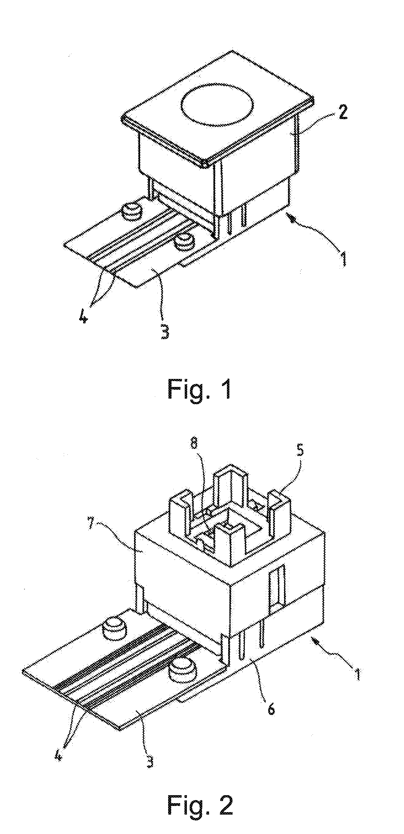
[0024]The switch arrangement of FIG. 1 comprises a switch housing 1 and a cap 2. Cap 2 may be modified according to customer requirements, it may be furnished with perforations or translucent portions to allow the light from a light source arranged inside switch housing 1 to pass through.

[0025]A foil 3 including electrically conductive pathways 4 extends into the interior of switch housing 1.

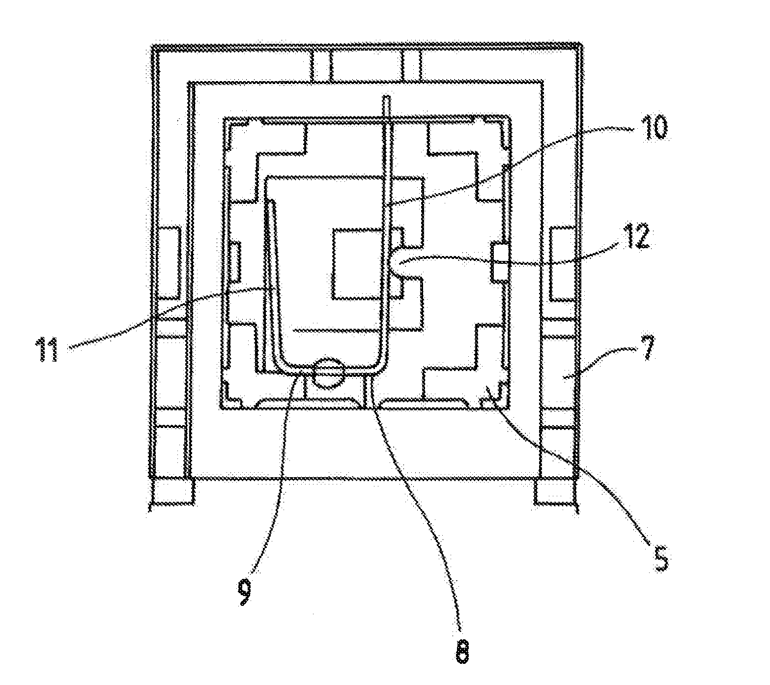
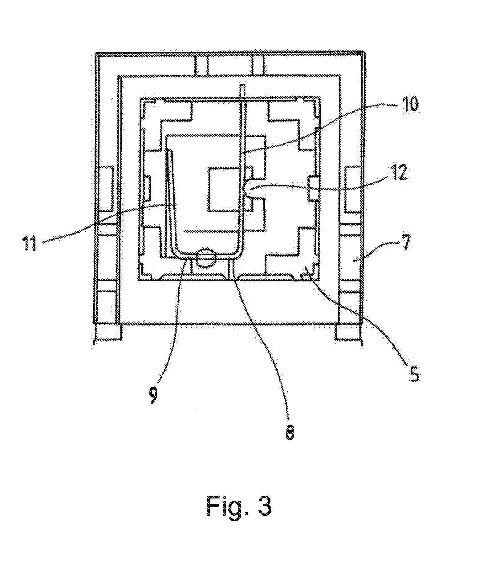
[0026]When cap 2 is removed, as shown in FIG. 2, It can be seen that cap 2 is placed over a button 5. Button 5 is guided inside switch housing 1, and is able to assume two fixed switching states. Switch housing 1 is made from a base component 6 and another component 7 that is fastened on top of base component 6 and has a guide track 13. A spring 8 is inserted into button 5.

[0027]FIG. 3 shows spring 8. It is configured as a section of wire bent into a U-shape, it has a U-base 9, a protruding U-leg 10 and another U-leg 11. U-base 9 is attached fixedly to button 5. Protruding U-leg 10 lies flush ag...


PUM


Abstract

An electrical switch arrangement has a switch housing and a button guided in the switch housing. The button can be brought into two fixed switching states. A display indicates when at least one of the switching states is reached. A U-shaped spring is arranged inside the button approximately at right angles to the direction of movement the button. The spring is guided in a guide track formed in sections of the switch housing.

Description

CROSS REFERENCE TO RELATED APPLICATIONS[0001]This non-provisional patent application claims priority under 35 U.S.C. §119(a) from Patent Application No. 102012005960-4 filed in Germany on Mar. 23, 2012, the entire contents of which is incorporated herein by reference.FIELD OF THE INVENTION[0002]This invention relates to an electrical switch arrangement and in particular, to a switch having two fixed switching states and a display which shows when at least one of the switching states has been reached.BACKGROUND OF THE INVENTION[0003]Such electrical switching arrangements are used for a variety of purposes, for example in automobiles in which when a switch is operated the driver and / or the front passenger must be able to see that it has been operated. Examples of such include a switch for the electric rear windscreen heater or also a switch for the hazard warning lights system. With these switches, a switching state is indicated by a visual display, and this visual display signals tha...

Claims


Application Information

Patent Timeline
IPC IPC(8): H01H13/20
CPCH01H13/20H01H13/562H01H13/023
Inventor KOEPSELL, MARTIN
Owner JOHNSON ELECTRIC SA
Features
  • Generate Ideas
  • Intellectual Property
  • Life Sciences
  • Materials
  • Tech Scout
  • Unparalleled Data Quality
  • Higher Quality Content
  • 60% Fewer Hallucinations
Learn More