

Light bulb shaped lamp and lighting apparatus
- Summary
- Abstract
- Description
- Claims
- Application Information
AI Technical Summary
Benefits of technology
Problems solved by technology
Method used
Image

Examples
embodiment 1
(Overall Structure of Light Bulb Shaped Lamp)
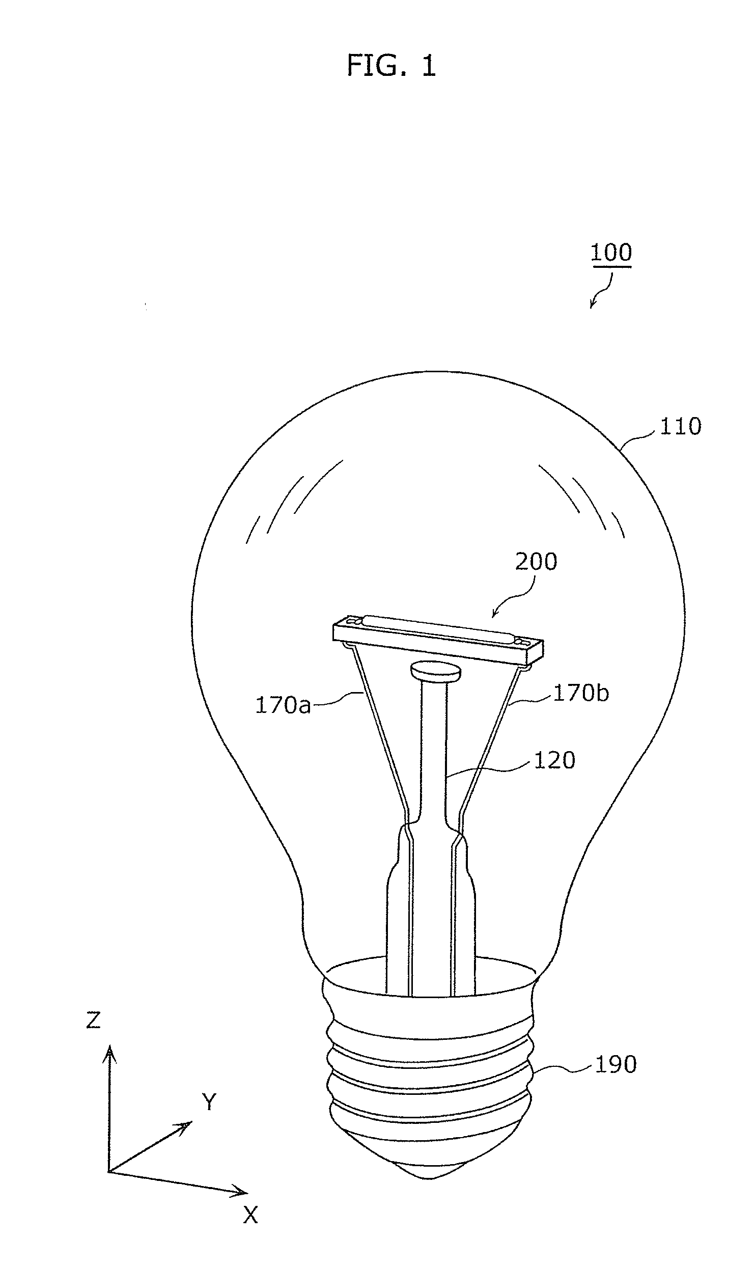
[0124]The overall structure of the light bulb shaped lamp 100 according to the embodiment 1 shall be described with reference to FIG. 1 to FIG. 3.
[0125]FIG. 1 is a perspective view of the light bulb shaped lamp according to the embodiment 1. In FIG. 1 to FIG. 3, the X, Y, and Z-axis directions are orthogonal to each other. The X, Y, and Z-axis directions in the drawings below are orthogonal to each other.
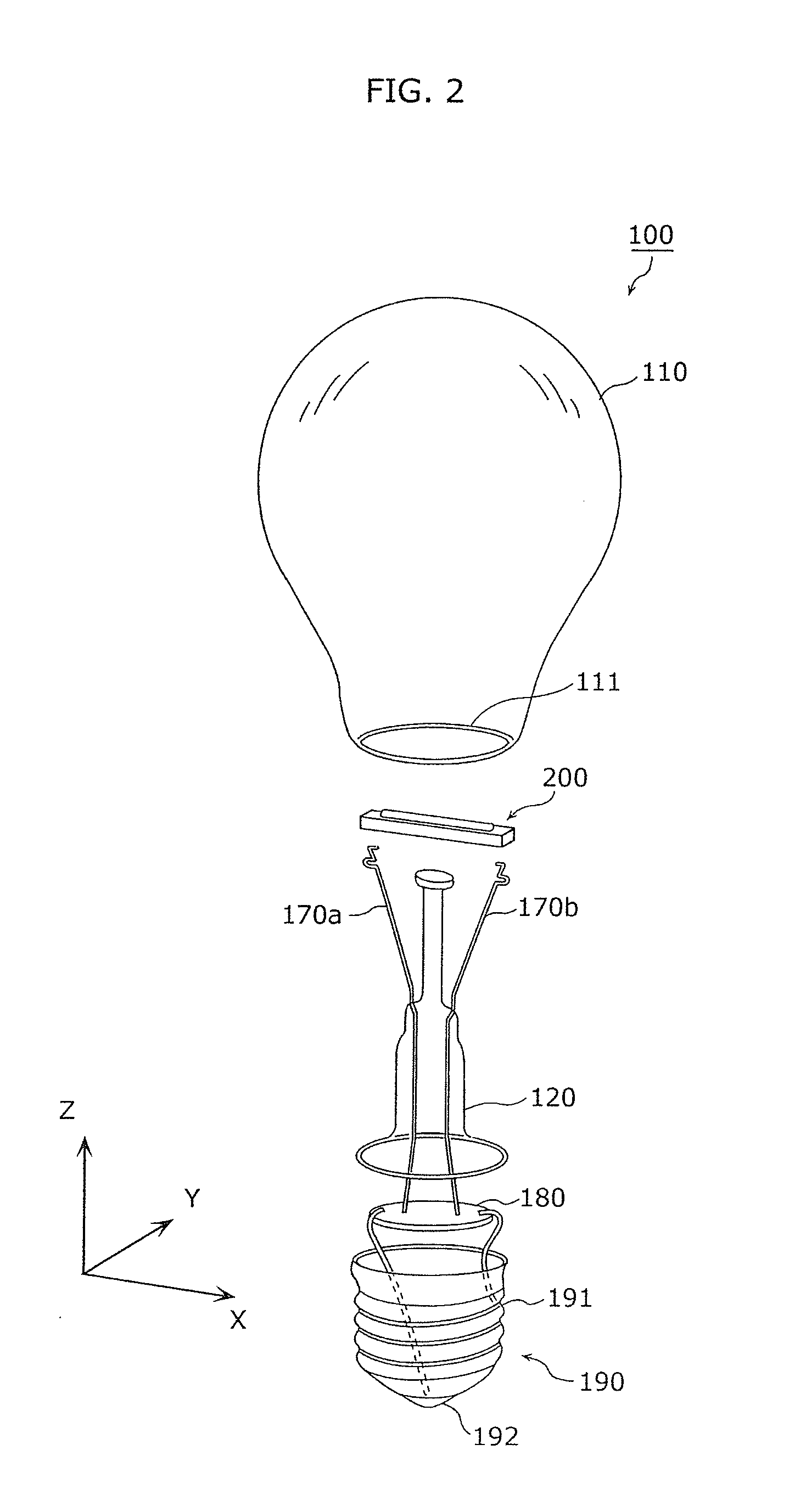
[0126]FIG. 2 is an exploded perspective view of the light bulb shaped lamp according to the embodiment 1.
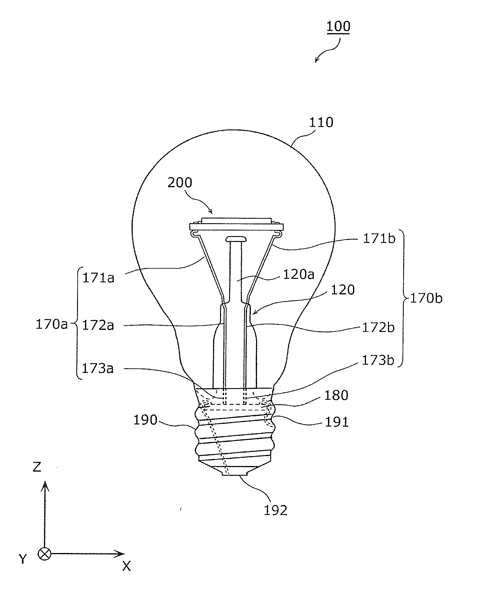
[0127]FIG. 3 is a front view of the light bulb shaped lamp according to the embodiment 1. Note that, in FIG. 3, a lighting circuit 180 and part of lead wires 170a and 170b for power supply and for support which are positioned inside a base 190 are illustrated in dotted lines.
[0128]The light bulb shaped lamp 100 is a light bulb including a translucent globe 110 and a base 190 attached to the globe 110. An LED module 200 in which a semic...
embodiment 2
(Overall Structure of Light Bulb Shaped Lamp)
[0509]The overall structure of the light bulb shaped lamp 100A according to the embodiment 2 shall be described with reference to FIG. 23 to FIG. 25.
[0510]FIG. 23 is a perspective view of the light bulb shaped lamp according to the embodiment 2.
[0511]FIG. 24 is an exploded perspective view of the light bulb shaped lamp according to the embodiment 2.
[0512]FIG. 25 is a front view of the light bulb shaped lamp according to the embodiment 2.
[0513]The light bulb shaped lamp 100A is different from the light bulb shaped lamp 100 in FIG. 1 in that lead wires 130a and 130b are provided instead of the lead wires 170a and 170b, and an LED module 200N is provided instead of the LED module 200. The rest of the structure of the light bulb shaped lamp 100A is identical to the light bulb shaped lamp 100. Accordingly, the detailed description is not repeated.
[0514]The lead wires 130a and 130b have the same structure and function as the lead wires 170a and...
embodiment 3
(Overall Structure of Light Bulb Shaped Lamp)
[0714]The overall structure of the lightbulb-shaped lamp 100B according to the embodiment 3 shall be described with reference to FIG. 38 to FIG. 40.
[0715]FIG. 38 is a front view of the lightbulb-shaped lamp according to the embodiment 3.
[0716]FIG. 39 is an exploded perspective view of the lightbulb-shaped lamp according to the embodiment 3.
[0717]FIG. 40 is a perspective view of the lightbulb-shaped lamp according to the embodiment 3.
[0718]The lightbulb-shaped lamp 100B is different from the lightbulb-shaped lamp 100 in FIG. 1 in that lead wires 140a and 140b are provided instead of the lead wires 170a and 170b, and an LED module 201A instead of the LED module 200. The rest of the structure of the lightbulb-shaped lamp 100B is identical to the lightbulb-shaped lamp 100. Accordingly, the detailed description is not repeated.
[0719]The lead wires 140a and 140b have the same structure and function as the lead wires 170a and 170b. Accordingly, ...
PUM
 Abstract
Description
Claims
Application Information