Window Blind Solar Energy Management System

Inactive Publication Date: 2013-09-26
MBC VENTURES INC
View PDF9 Cites 9 Cited by
  • Summary
  • Abstract
  • Description
  • Claims
  • Application Information

AI Technical Summary

Benefits of technology

[0016]The objective of the heating function of the system described herein is to convert the incoming solar beam radiation into radiant thermal energy that can be projected deep into the room to enhance the thermal comfort of the occupants. The thermal comfort of a building occupant is a function of the temperature and velocity of the immediately surrounding air as well as the temperature and radiant properties of the internal surfaces of the room. If a person is sitting near a large window which has a low temperature of the glass surface, he may feel cold even though the air temperature near his skin is warm. This is because his body will be radiating heat to the window because the window surface temperature is colder than his skin temperature. Conversely, it is possible for one to feel comfortable in a room with relatively low air temperature if the temperature of the walls and floor are relatively high. This is the principle behind radiant floor heating in homes and commercial buildings whereby energy savings can be achieved by lower indoor air temperatures while maintaining or improving comfort.
[0017]In terms of the system described herein, the primary desired characteristic for heating is to absorb the incoming solar radiation to heat the room. Secondarily, it is desirable to have a significant fraction of the heat be radiated into the room as opposed to convected as hot air. Heat that is radiated from the window blind counters the “cold window” effect and can instantaneously project the heat to the occupant and the surfaces in the room, as opposed to heating the air alone and relying on ventilation to move the heat into the roo

Problems solved by technology

This attenuation, while improving the lighting aspects, is undesirable to the extent that it i

Method used


Image

  • Window Blind Solar Energy Management System
  • Window Blind Solar Energy Management System
  • Window Blind Solar Energy Management System

Examples


Example

[0031]The following description is of a particular embodiment of the invention, set out to enable one to practice an implementation of the invention, and is not intended to limit the preferred embodiment, but to serve as a particular example thereof. Those skilled in the art should appreciate that they may readily use the conception and specific embodiments disclosed as a basis for modifying or designing other methods and systems for carrying out the same purposes of the present invention. Those skilled in the art should also realize that such equivalent assemblies do not depart from the spirit and scope of the invention in its broadest form.

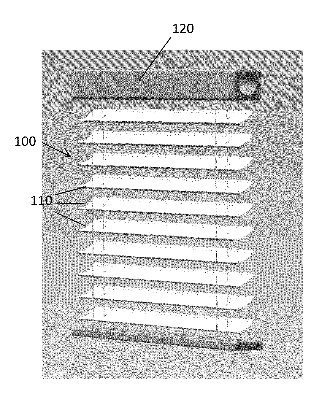
[0032]FIGS. 1(a) and 1(b) provide front and rear perspective views, respectively, of a window blind solar energy management system (shown generally at 100) according to certain aspects of an embodiment of the invention. As shown in FIGS. 1(a) and 1(b), the system has the superficial appearance of a typical Venetian blind having multiple louvers ...


PUM


Abstract

Disclosed is a window blind solar energy management system for capturing solar energy to manage illumination and temperature within a defined space. Blinds comprising curved louvers are hung from the internal frame of a window, each louver having a concave, highly reflecting specular mirrored surface that focuses incoming solar beam radiation onto a thin area on the back of the adjacent louver. The angle of the louvers is adjusted by an integral automatic controller so that the thin strip of light can be focused on one or two of three regions on the back of the adjacent louver which are designed to either reflect, absorb, or reject the incoming light.

Description

CROSS REFERENCE TO RELATED APPLICATION[0001]This application is based upon and claims benefit of copending U.S. Provisional Patent Application Ser. No. 61 / 615,389 entitled “Window Blind Solar Energy Management System,” filed with the U.S. Patent and Trademark Office on Mar. 26, 2012 by the inventor herein, and copending U.S. Provisional Patent Application Ser. No. 61 / 703,606 entitled “Window Blind Solar Energy Management System,” filed with the U.S. Patent and Trademark Office on Sep. 20, 2012, the specifications of which are incorporated herein by reference in their entireties.FIELD OF THE INVENTION[0002]This invention relates to radiant energy management, and more particularly to systems for capturing solar energy to manage illumination and temperature within a defined space.BACKGROUND OF THE INVENTION[0003]As an architectural feature, a window provides daylight to an interior space and allows the building occupants a view to the outside. When direct beam solar radiation falls dir...

Claims


Application Information

Patent Timeline
IPC IPC(8): G02B17/00F24V50/00
CPCG02B17/006G02B17/00E06B9/386E06B9/303E06B2009/2417F21S11/007G02B19/0019G02B19/0042
Inventor TANDLER, JOHN JOSEPH
Owner MBC VENTURES INC
Why Eureka
Try Eureka