
Control techniques for photovoltaic power plants

a photovoltaic power plant and control technology, applied in the field of solar cells, can solve the problems of inability to respond to conditions, additional constraints on communication infrastructure and control response rates, and the practical challenges of coordinated control of multiple inverters operating in parallel in a large photovoltaic power plant that have not been fully explored or understood

Active Publication Date: 2013-09-26
ENPHASE ENERGY
View PDF6 Cites 45 Cited by
  • Summary
  • Abstract
  • Description
  • Claims
  • Application Information

AI Technical Summary

Benefits of technology

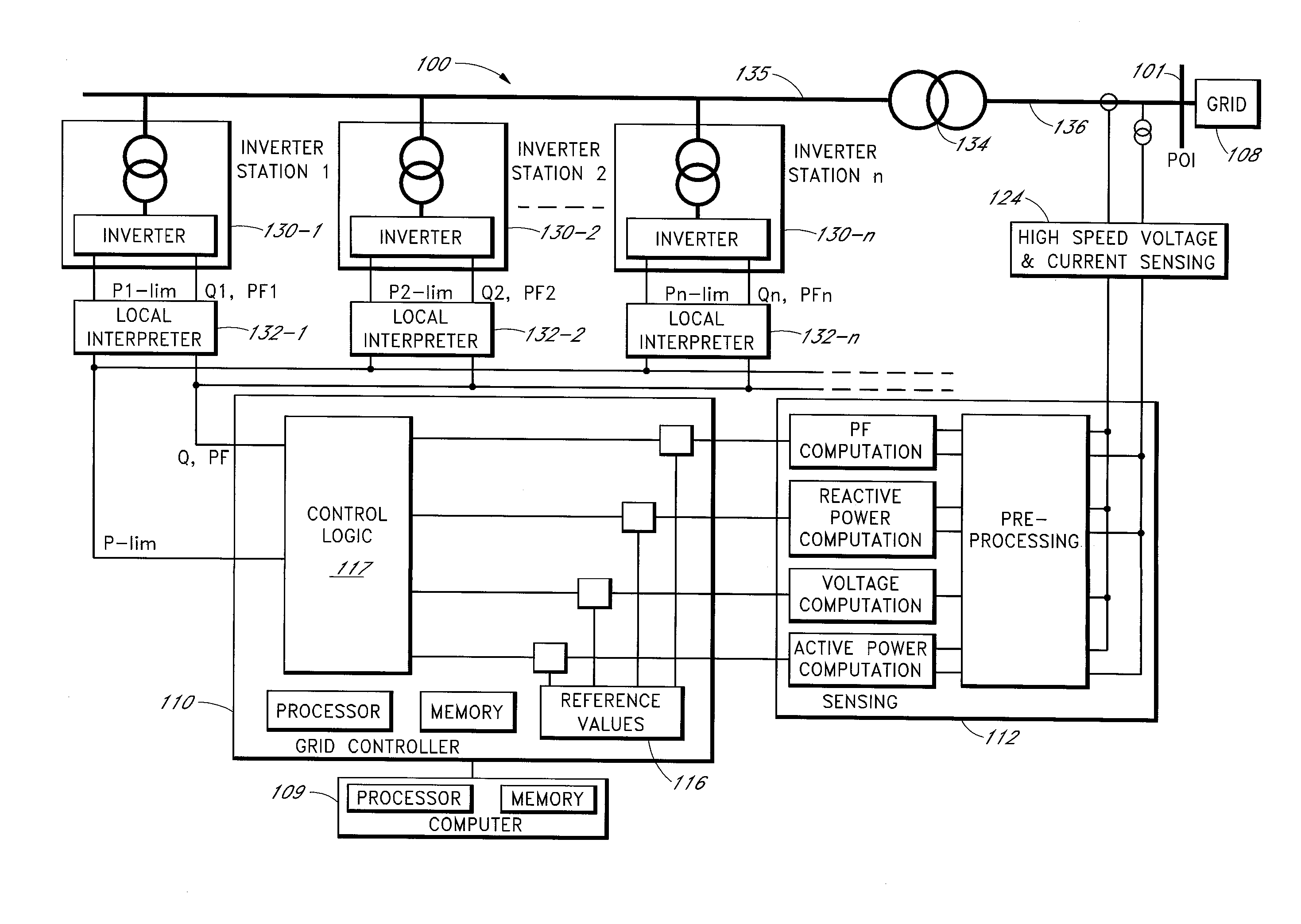
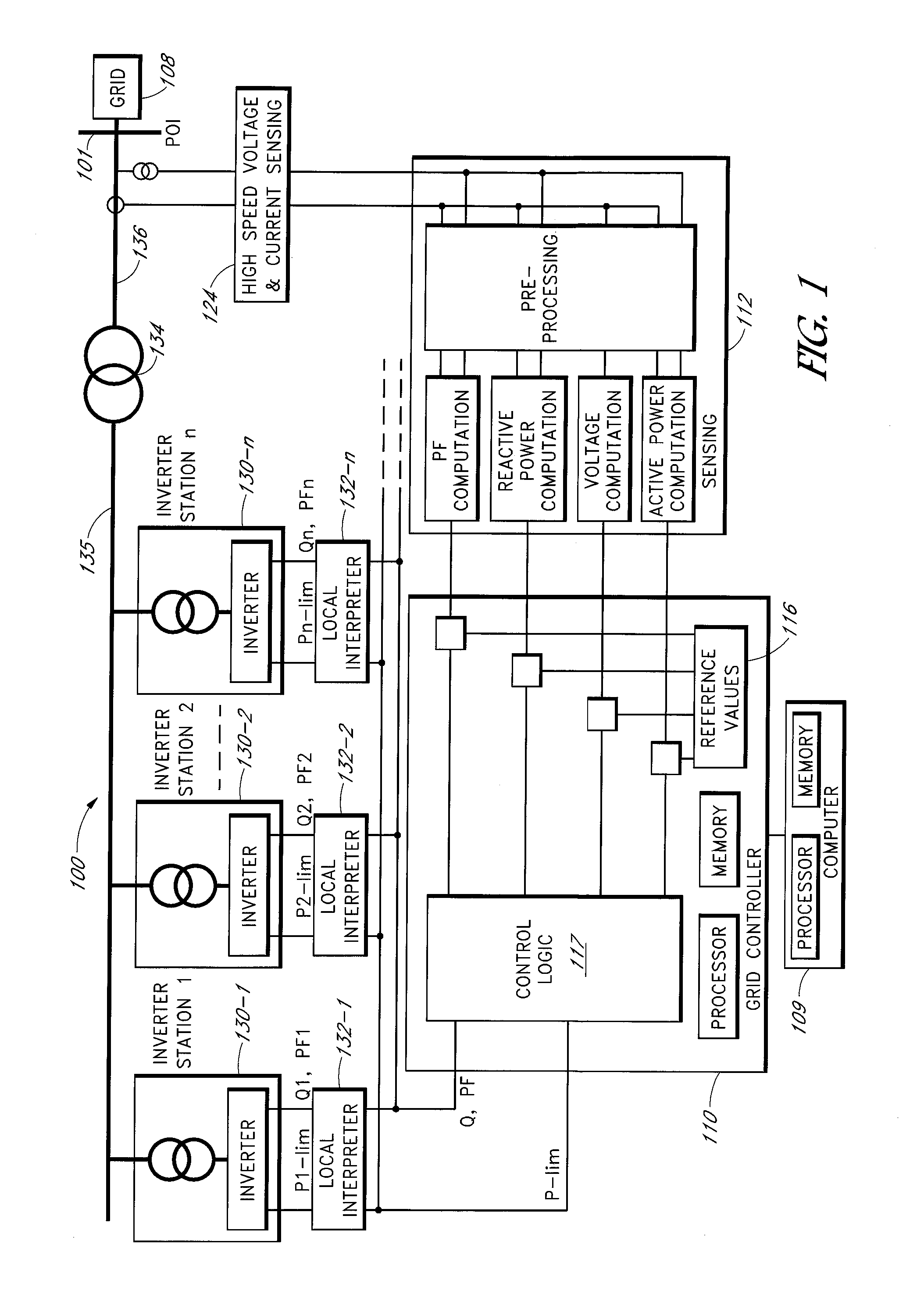
This patent describes a method for controlling the operation of a photovoltaic power plant. It involves using a global reactive power setpoint for multiple inverters, which converts the direct current generated by the solar cells into alternating current. Each inverter interprets this global setpoint and generates reactive power based on an equivalent impedance that represents the impedances of all inverters. This method allows for more efficient and accurate control of the inverters, resulting in improved performance of the photovoltaic power plant.

Problems solved by technology

While utility grade inverters, due to their topology and controllability, offer extended capabilities, such as controlled reactive power delivery, frequency-power droop control, and fault-ride-through, practical challenges associated with coordinated control of multiple inverters operating in parallel in a large photovoltaic power plant have not been fully explored or understood.
Inverters are highly flexible and controllable devices, but they are only capable of responding to conditions present at their terminals.
The distances of the inverters to the POI with the utility grid and the limitations in sensing of signals at the POI impose additional constraints on the communication infrastructure and on the achievable control response rates.

Method used


Image

  • Control techniques for photovoltaic power plants
  • Control techniques for photovoltaic power plants
  • Control techniques for photovoltaic power plants

Examples


Embodiment Construction

[0020]In the present disclosure, numerous specific details are provided, such as examples of apparatus, components, and methods, to provide a thorough understanding of embodiments of the invention. Persons of ordinary skill in the art will recognize, however, that the invention can be practiced without one or more of the specific details. In other instances, well-known details are not shown or described to avoid obscuring aspects of the invention.

[0021]In general, the generic optimal reactive power scheduling problem for a large photovoltaic power plant can be described as follows. For an appropriately chosen midpoint node where all clusters of inverters are connected, given a set of midpoint nodal variables vm(k) and qm(k), and inverter variables: pi(k), i=1,2, . . . , N, compute Qi(k), i=1,2, . . . , N, which minimizes a selected objective function J(k), under the constraint that

|qi(k)|≦qimax(k)   (EQ. 1)

[0022]where qimax(k), the reactive power limit of inverter i, is dependent la...


PUM


Abstract

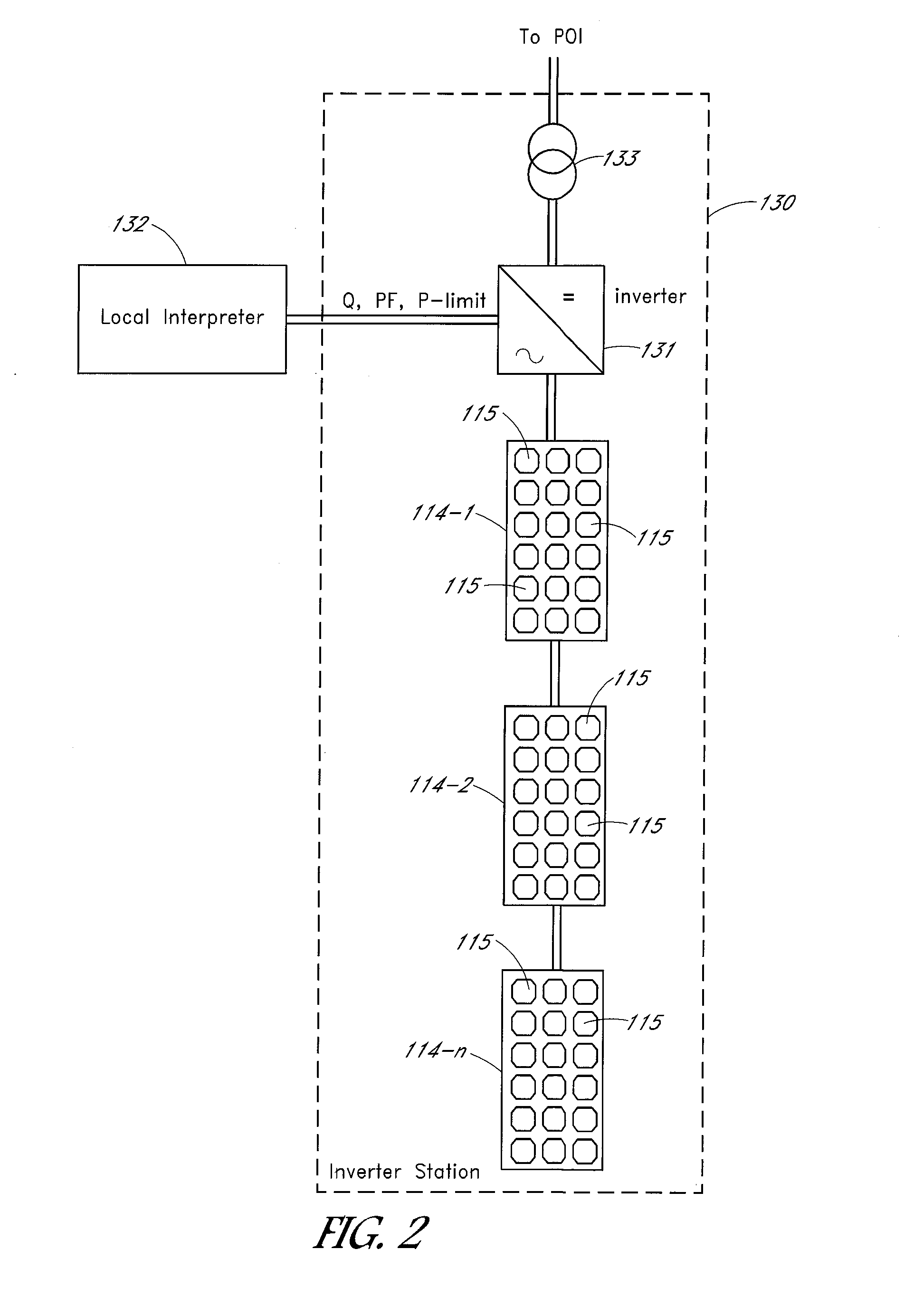
A photovoltaic power plant includes solar cells and inverters that convert direct current generated by the solar cells to alternating current. The reactive powers generated by the inverters are based on a reactive power generated by a virtual inverter. The virtual inverter has an equivalent impedance representing the impedances of the inverters in the photovoltaic power plant. The reactive power setpoints of the inverters may be received from a local interpreter. The local interpreter may generate the reactive power setpoints from a global reactive power setpoint generated by a grid controller.

Description

TECHNICAL FIELD[0001]Embodiments of the subject matter described herein relate generally to solar cells. More particularly, embodiments of the subject matter relate to operation and control of photovoltaic power plants.BACKGROUND[0002]Photovoltaic power plants employ solar cells to convert solar radiation to electrical energy. Photovoltaic power plants also include photovoltaic inverters (“inverters”), which convert direct current (DC) generated by the solar cells to alternating current (AC) suitable for delivery to a point of interconnect (POI) with a utility grid through a network of transformers and transmission lines.[0003]The role of inverters in supporting grid integration requirements in the context of large photovoltaic power plants is still evolving. While utility grade inverters, due to their topology and controllability, offer extended capabilities, such as controlled reactive power delivery, frequency-power droop control, and fault-ride-through, practical challenges asso...

Claims


Application Information

Patent Timeline
Patent Type & Authority Applications(United States)
IPC IPC(8): H02M7/44
CPCH02J3/383Y02E40/30Y02E10/563H02J3/18Y02P80/14H02J2300/24H02J3/381Y02E10/56H02J3/50H02M7/44
Inventor SIVAKUMAR, SESHADRILIAN, JIYONG
Owner ENPHASE ENERGY
Learn More