
Large Mode Area Optical Fibers With Bend Compensation

a technology of optical fibers and bend compensation, applied in the field of large mode area (lma) fibers, can solve the problems of reducing the ability of various fiber designs to selectively suppress homs, limiting the scaling area, and degrading the beam quality, so as to improve system performance, improve beam quality, and high degree of attenuation of homs

Active Publication Date: 2013-09-26
OFS FITEL LLC
View PDF2 Cites 50 Cited by
  • Summary
  • Abstract
  • Description
  • Claims
  • Application Information

AI Technical Summary

Benefits of technology

The invention allows for a fiber to be bent or coiled to a specific point with a uniform refractive index profile. This means the fiber can be deployed without needing a specific orientation.

Problems solved by technology

However, larger area fibers typically support several or many modes, increasing the likelihood that HOMs will also propagate in the fiber and undergo amplification, thereby degrading the quality of beam.
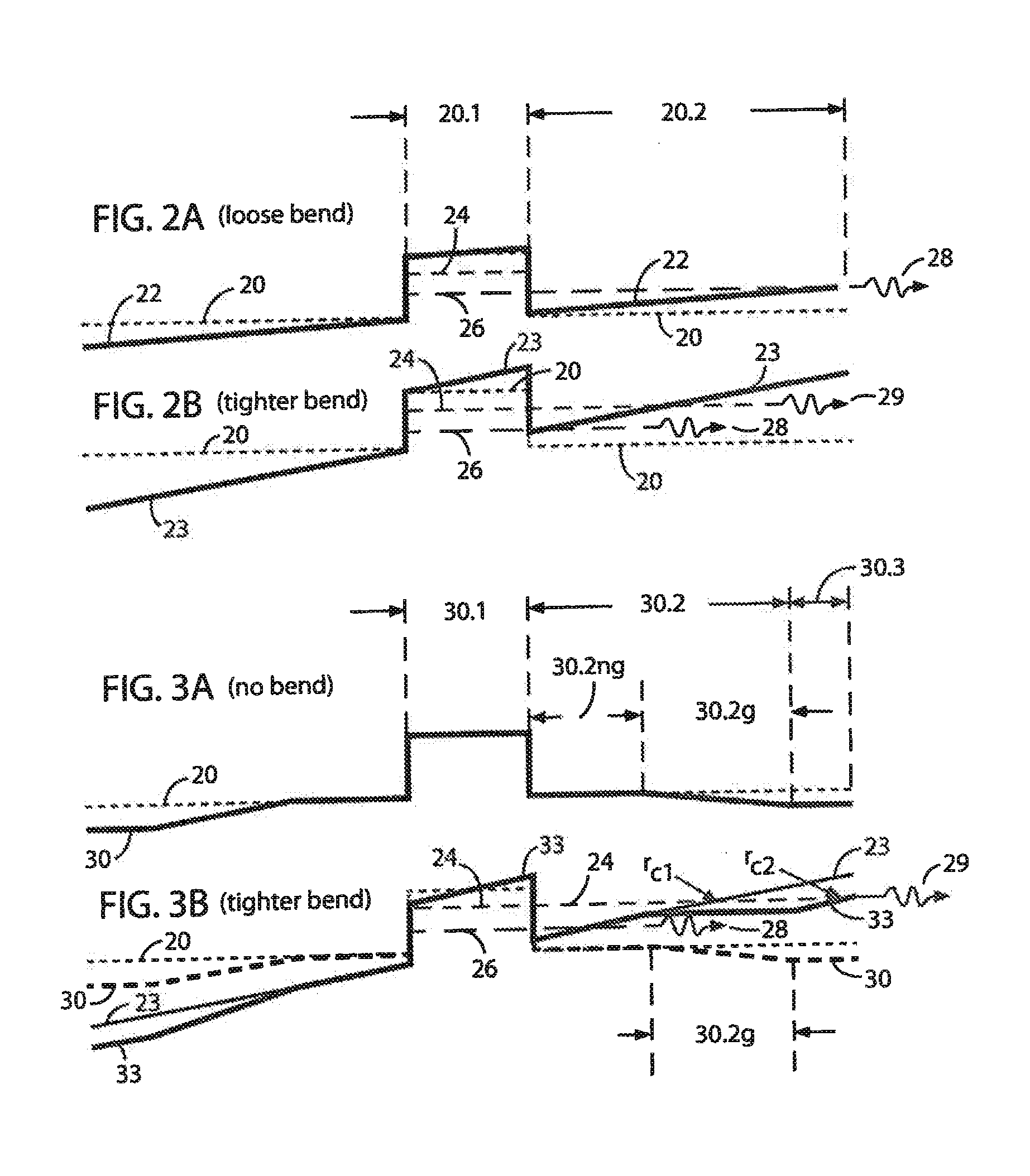
Bends in the fiber exacerbate this problem—they reduce the ability of various fiber designs to selectively suppress HOMs while ensuring propagation of the fundamental mode at power levels that satisfy typical performance requirements.
Macrobend loss is often the dominant source of loss, bend distortion limits the scaling of area, and bends degrade single-mode operation, as noted above, by limiting the degree to which unwanted HOMs can be selectively suppressed.
However, this strategy may be difficult to implement.

Method used


Image

  • Large Mode Area Optical Fibers With Bend Compensation
  • Large Mode Area Optical Fibers With Bend Compensation
  • Large Mode Area Optical Fibers With Bend Compensation

Examples


examples

[0082]Several ABC fiber designs of the type described above have been simulated with cell spacing L, core diameter Dcore=2r1=5 L (19 cells within the core region) and with inner cladding sizes Di-clad=(r2−r1)=12 L [Di-clad / Dcore=r2r / rcore=2.4] or 18 L [Di-clad / Dcore=r2 / rcore=3.6]. In an illustrative design with L=10, the bend-compensating gradient (slope of the inner cladding region 70.2) corresponded to steps along the x-axis of approximately γxnsil / Rb, or approximately 0.8×10⁻⁴, as shown in FIG. 7A, where nsil is the index of pure silica (a good approximation to ncore as indicated earlier) and Rb is assumed to be 15 cm, a fairly large but practical coil size.

[0083]A relatively small core-to-inner cladding contrast was used (for the approximate step-index core profile 70c, FIG. 7B) to enhance leakage of HOMs while provide acceptable calculated bend loss for the fundamental mode of 0.1 dB / m. Our simulations confirmed that very large mode area (Aeff=2160 μm2) is compatible with large...


PUM


Abstract

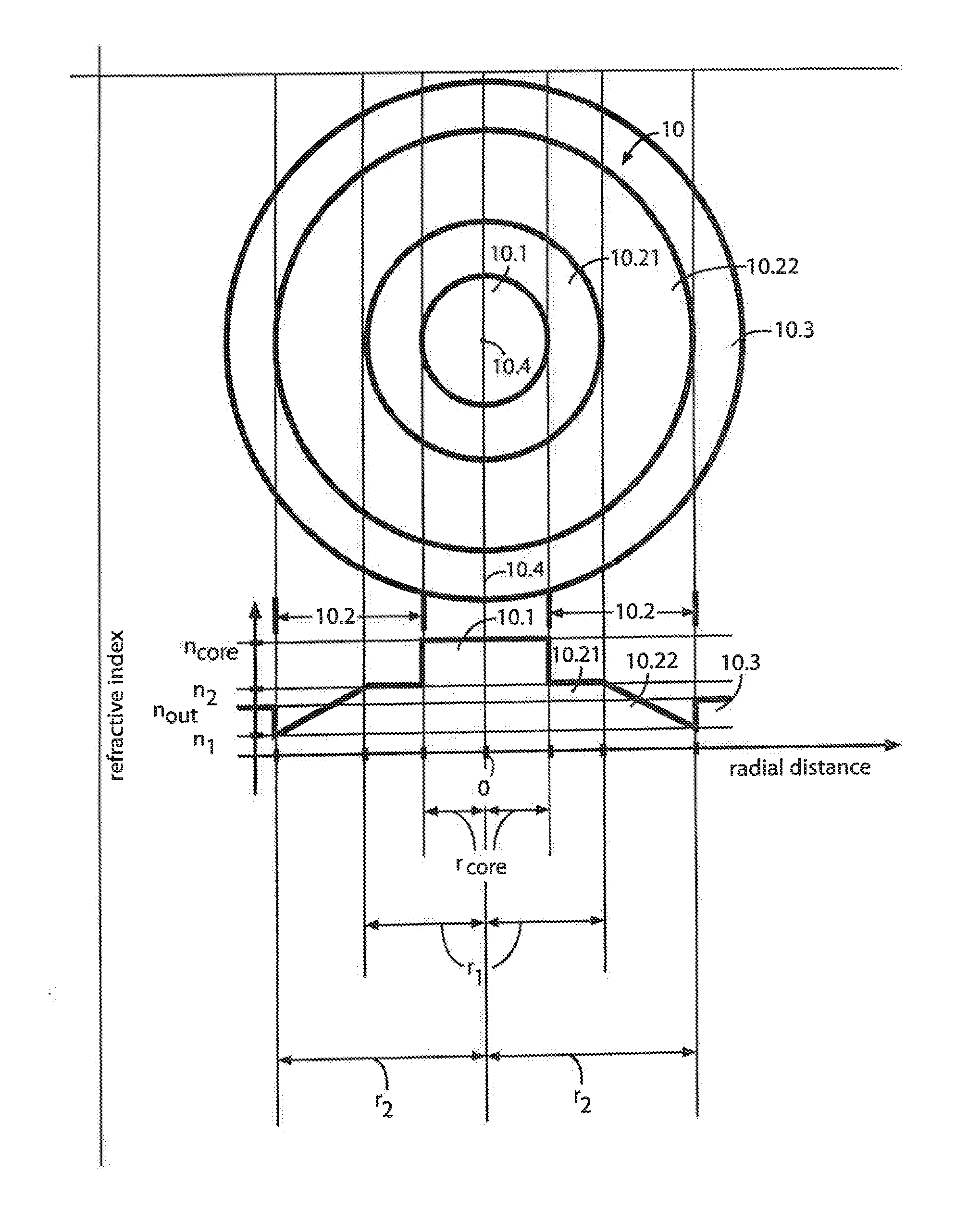
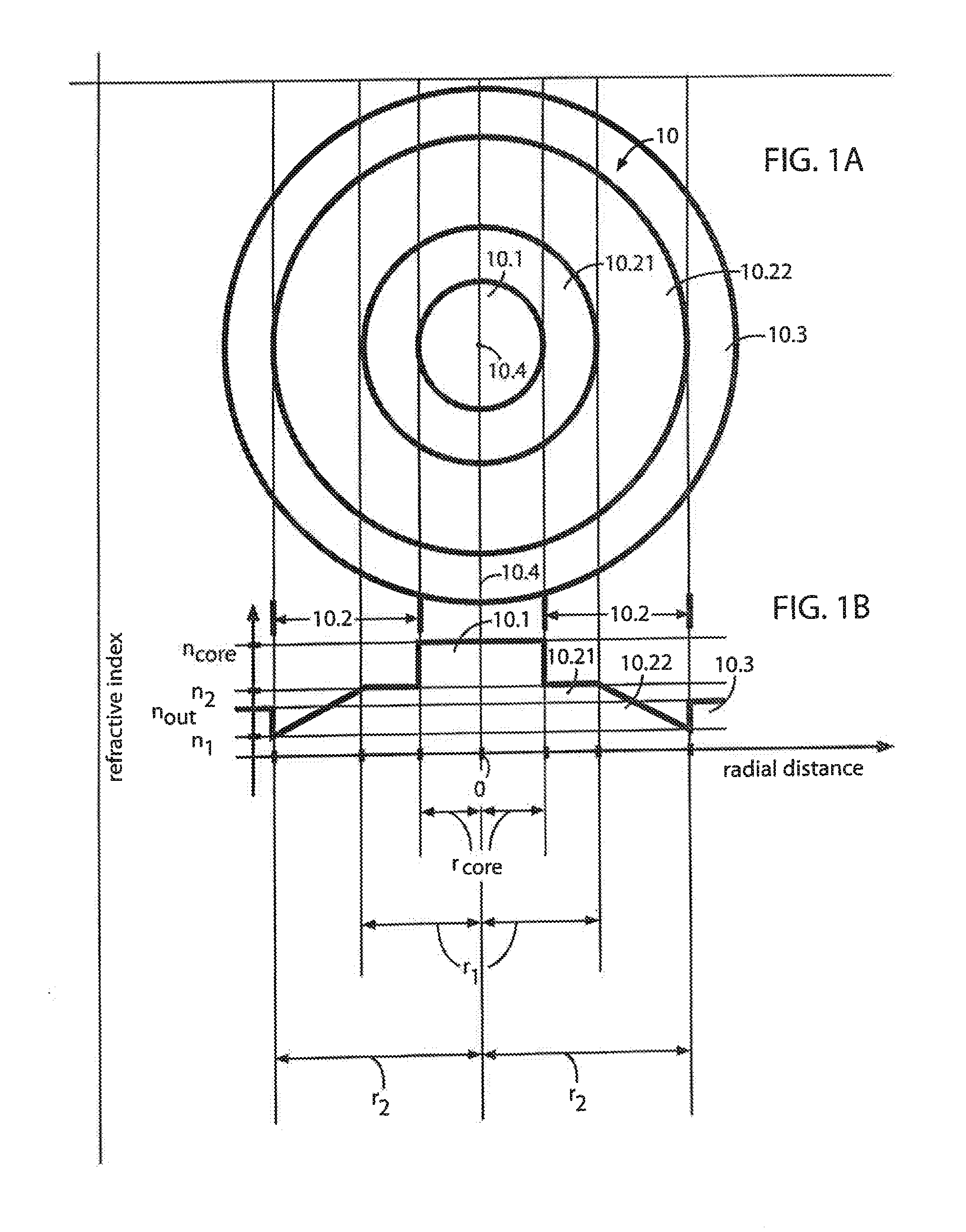
A LMA, single-mode optical fiber comprises a core region, an inner cladding region surrounding the core region, and an outer cladding region surrounding the inner cladding region. The inner cladding region is configured to provide bend compensation. In one embodiment the index profile of the inner cladding region is graded with a slope of γncore / Rb, where ncore is the refractive index of the core region, Rb is the bend radius, and γ=0.6-1.2. In addition, the inner cladding is annular and the ratio of its outer radius to its inner radius is greater than 2. In a preferred embodiment this ratio is greater than 3. The overall index profile may be symmetric or asymmetric.

Description

CROSS-REFERENCE TO RELATED APPLICATIONS[0001]This application claims priority from two provisional applications: Ser. No. 61 / 506,631 filed on Jul. 11, 2011 and Ser. No. 61 / 419,420 filed on Dec. 3, 2010.BACKGROUND OF THE INVENTION[0002]1. Field of the Invention[0003]This invention relates to large-mode-area (LMA) fibers designed to compensate for the effects of bends in the fiber and to suppress higher-order modes (HOMs) and, more particularly to high power optical amplifiers that incorporate such LMA fibers.[0004]2. Discussion of the Related Art[0005]Optical fiber amplifiers have great impact in diverse applications ranging from high power devices used for cutting, welding and range finding to lower power devices used to amplify optical carrier signals in telecommunication systems. In the former case, the high power amplifier utilizes a gain-producing fiber (GPF; e.g., a LMA fiber doped with suitable rare-earth species or chromium) and a source of pump light to amplify signal light ...

Claims


Application Information

Patent Timeline
Patent Type & Authority Applications(United States)
IPC IPC(8): G02B6/028
CPCG02B6/02009G02B6/0283G02B6/0365G02B6/02019
Inventor FINI, JOHN M.NICHOLSON, JEFFREY W.
Owner OFS FITEL LLC
Learn More