
Removable heater assembly for a vaporizer

a heater and assembly technology, applied in the field of vaporizers, can solve the problems of time-consuming and costly repair, no longer working effectively of vaporizers, waste of resources, etc., and achieve the effect of convenient removal and/or replacement, cost or time, and convenient removal of the heater assembly

Inactive Publication Date: 2013-09-26
WEST COAST GIFTS
View PDF5 Cites 3 Cited by
  • Summary
  • Abstract
  • Description
  • Claims
  • Application Information

AI Technical Summary

Benefits of technology

Facilitates quick and cost-effective replacement of the heater assembly without requiring professional service, reducing waste and maintenance time.

Problems solved by technology

One problem that adversely affects vaporizers is that the heater assembly can fail or otherwise become damaged such that the vaporizer no longer works effectively, if at all.
That type of repair is time consuming and costly, and is often best left to qualified technicians.
That approach is wasteful and can be costly.

Method used


Image

  • Removable heater assembly for a vaporizer
  • Removable heater assembly for a vaporizer
  • Removable heater assembly for a vaporizer

Examples


Embodiment Construction

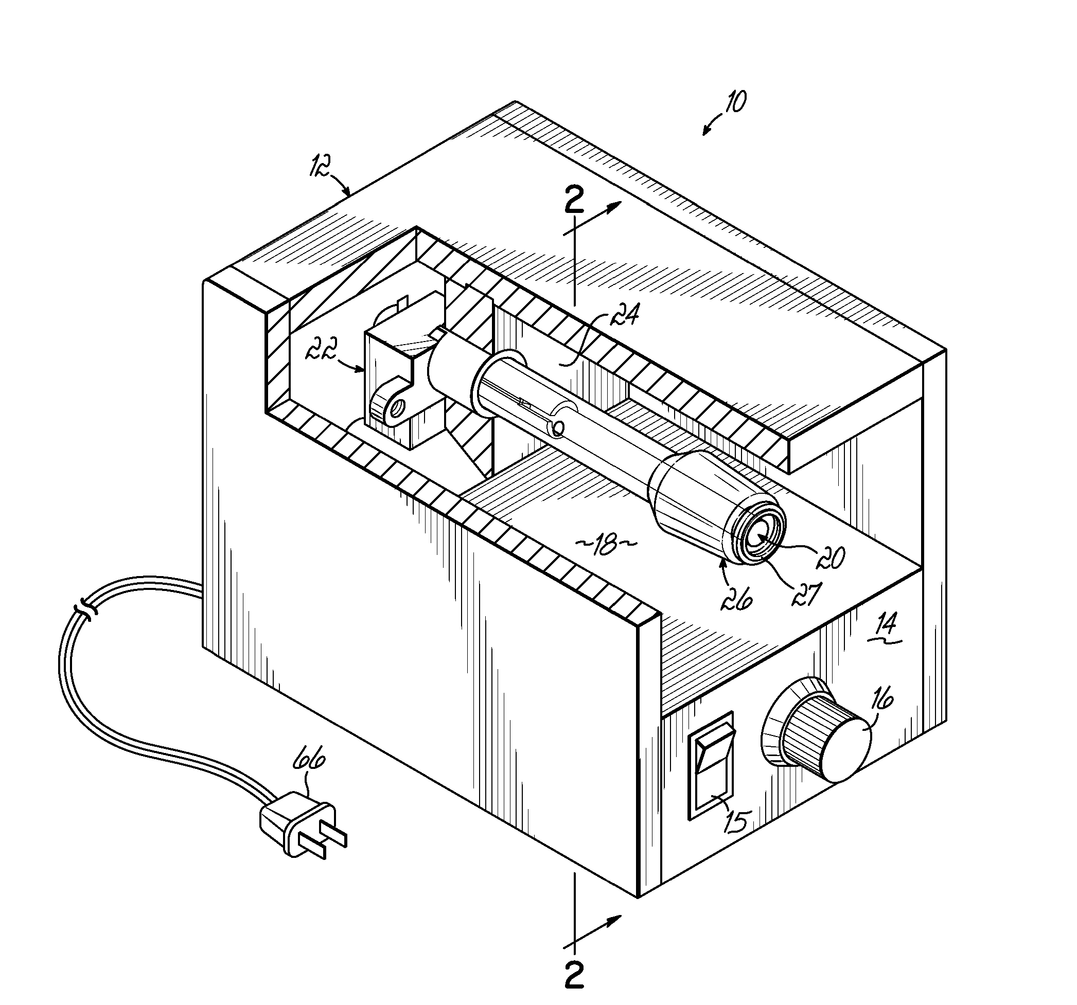
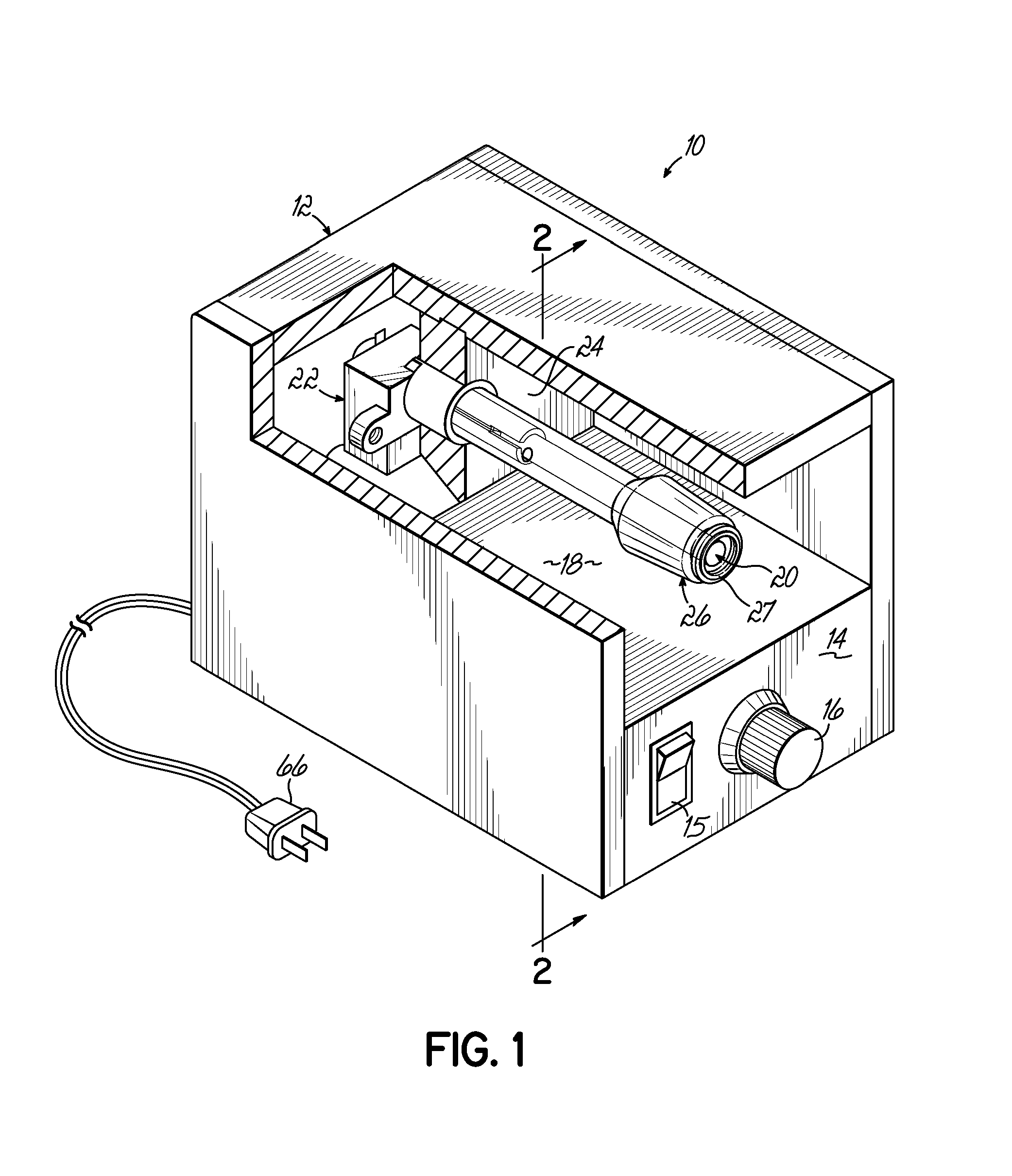
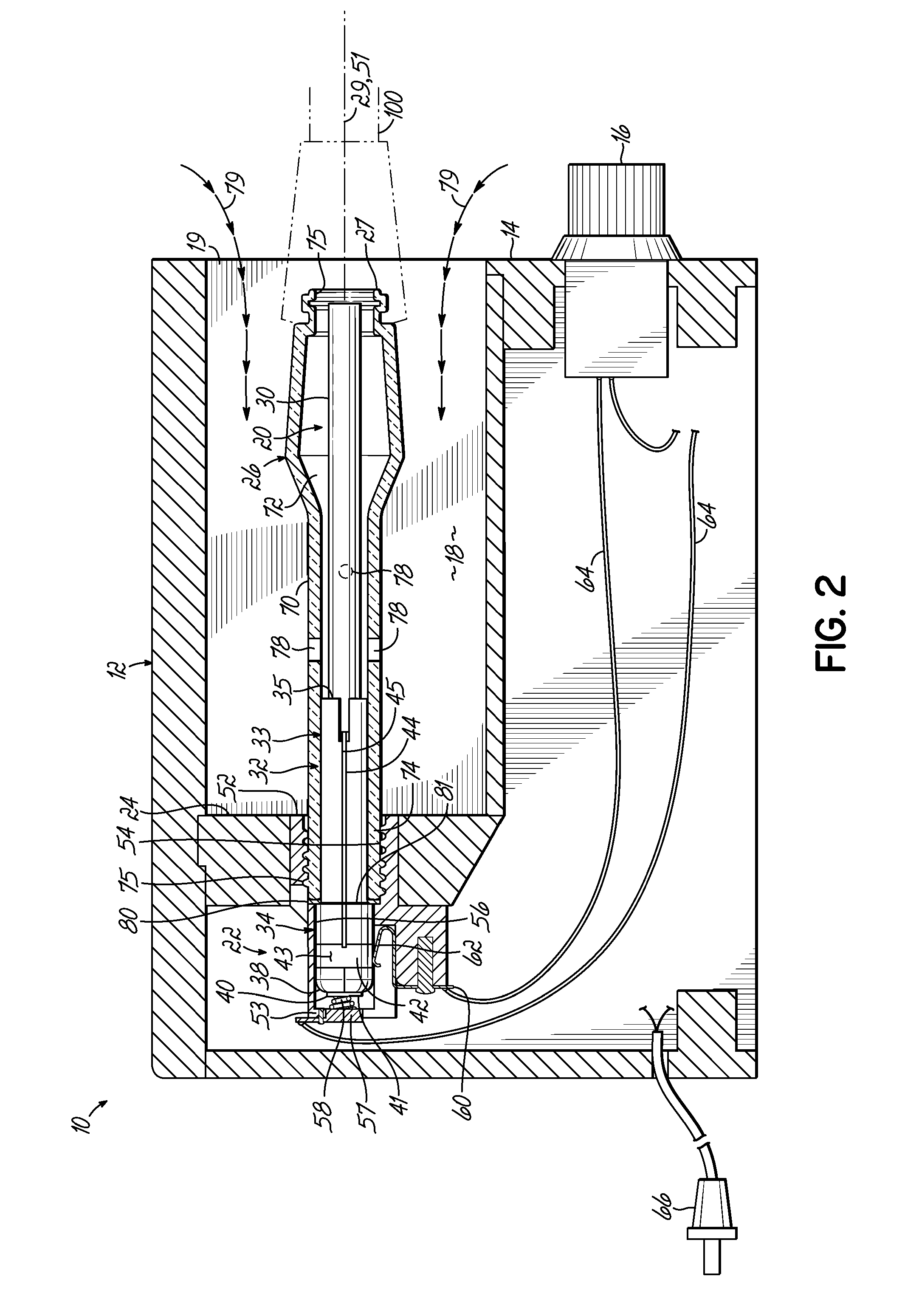
[0015]With reference to FIGS. 1 and 2 there is shown a vaporizer 10 having a housing 12, comprised of wood, plastic, glass, and / or metal and defining a front wall 14 to which is mounted an on / off switch 15 and a potentiometer 16 defining at least in part electric circuitry of vaporizer 10. A heater cavity 18 is defined in housing 12 and is exposed to ambient through front or upper opening 19 adjacent front wall 14. An embodiment of a replaceable heater assembly 20 is mechanically and electrically removably connected to a base 22 secured to a floor or back wall 24 of cavity 18 such that heater assembly 20 extends from floor or back wall 24 towards and adjacent to front or upper opening 19. A glass tubular member 26 is threadably removably connected to base 22 and over heater assembly 20 within cavity 18, with the front end 27 of glass tubular member 26 being accessible at front or upper opening 19.

[0016]With further reference to FIG. 3, heater assembly 20 is elongated along an axis 2...


PUM

PropertyMeasurementUnit
temperatureaaaaaaaaaa
pressureaaaaaaaaaa
currentaaaaaaaaaa

Abstract

A removable heater assembly 20 is provided for a vaporizer 10 by which to easily mechanically and electrically connect and disconnect the heater assembly 20 from a base 22 for removal and / or replacement thereof without requiring tools or specialized skills.

Description

RELATED APPLICATION[0001]This application is a continuation of U.S. application Ser. No. 12 / 883,740 filed Sep. 16, 2010, the disclosure of which is incorporated herein by reference in its entirety.FIELD OF THE INVENTION[0002]The present invention relates to vaporizers, and more particularly, to the heater assembly used in such vaporizers.BACKGROUND OF THE INVENTION[0003]Vaporizers have been in use for some time for purposes of aromatherapy or to vaporize herb medicaments. The vaporizers typically include a housing supporting a heater assembly. The heater assembly is typically mechanically affixed to the housing and hard-wired into the circuitry of the housing (such as an on / off switch and potentiometer for setting the temperature) so as to be effectively permanently mounted in the housing. Mounted over the heater assembly is a glass tubular member having one or more ports along its side and an opening at its front end to which to couple a negative source of pressure, such as a wand,...

Claims


Application Information

Patent Timeline
Patent Type & Authority Applications(United States)
IPC IPC(8): A61L9/03H05B3/44H05B3/06
CPCA61L9/03A61L2209/135F24H9/1863F24H3/0405Y10T29/49826F24H9/0063H05B3/141H05B3/44H05B3/06F24H3/0417
Inventor DURISEK, NIKLAUS R.
Owner WEST COAST GIFTS
Learn More