Enhanced Status Monitoring, Storage and Reporting for Optical Transceivers

a technology of optical transceivers and status monitoring, applied in electromagnetic transceivers, transmission monitoring, transmission monitoring/testing/fault measurement systems, etc., can solve problems such as the inability of conventional optical transceivers to provide information regarding monitored parameters, and achieve the effect of enhancing failure analysis and more accurate information

Active Publication Date: 2013-09-26
SOURCE PHOTONICS
View PDF5 Cites 25 Cited by
  • Summary
  • Abstract
  • Description
  • Claims
  • Application Information

AI Technical Summary

Benefits of technology

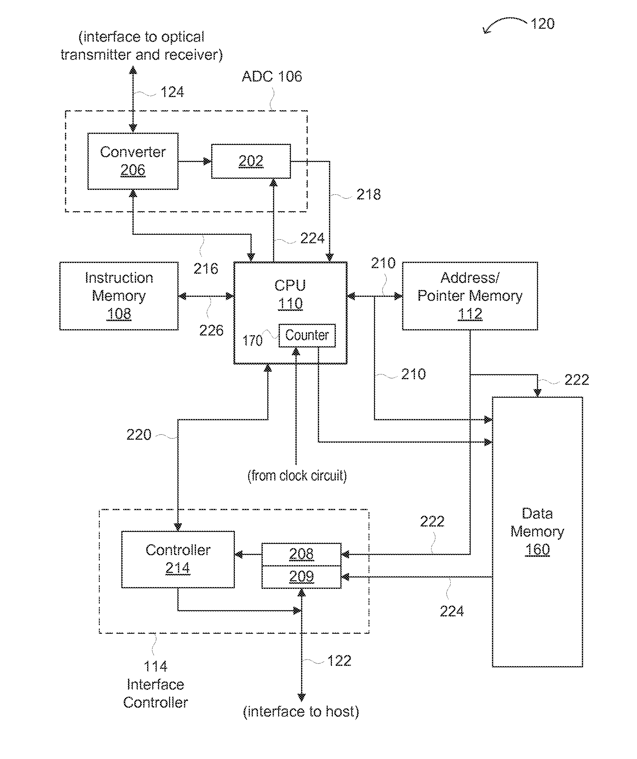
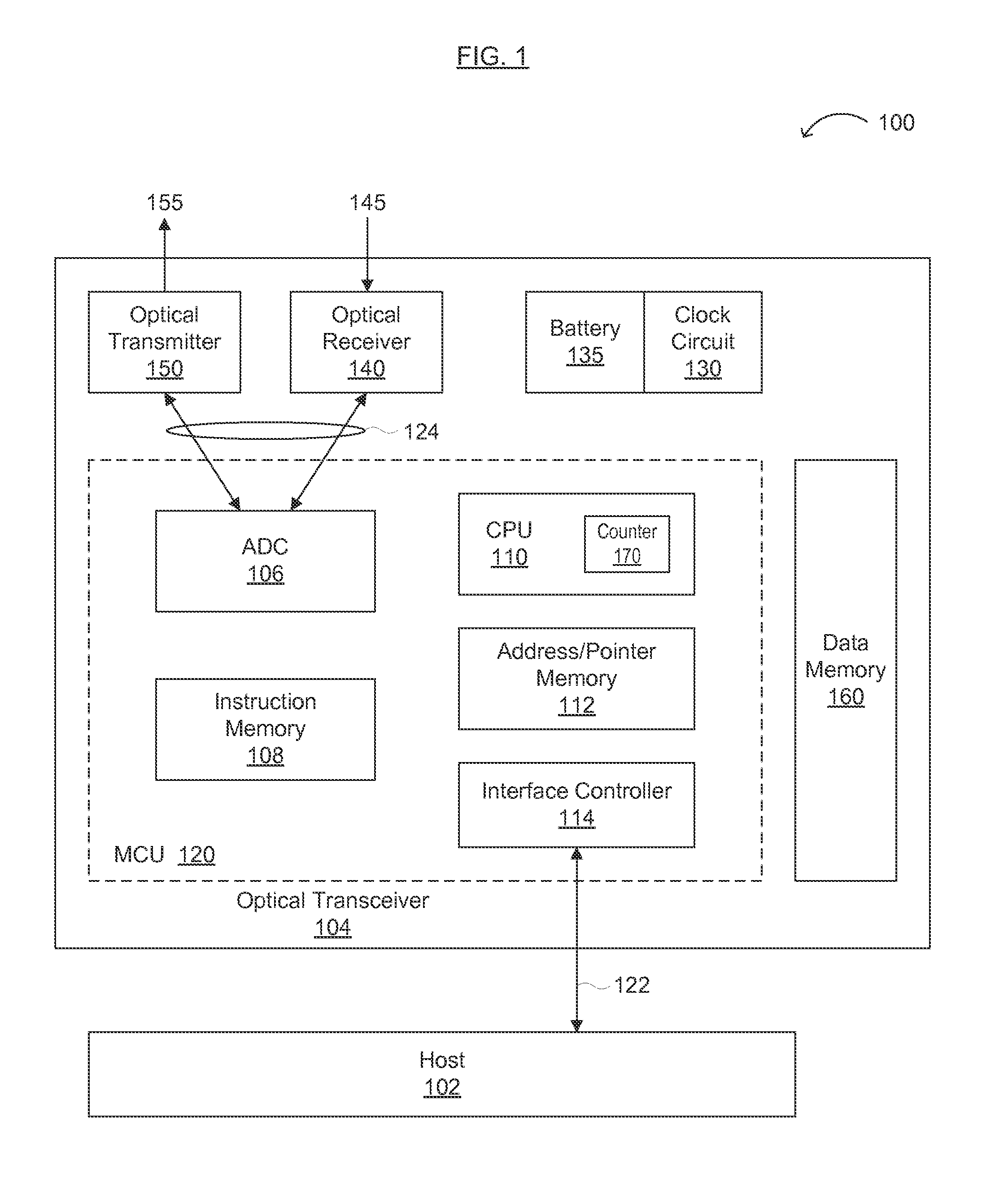
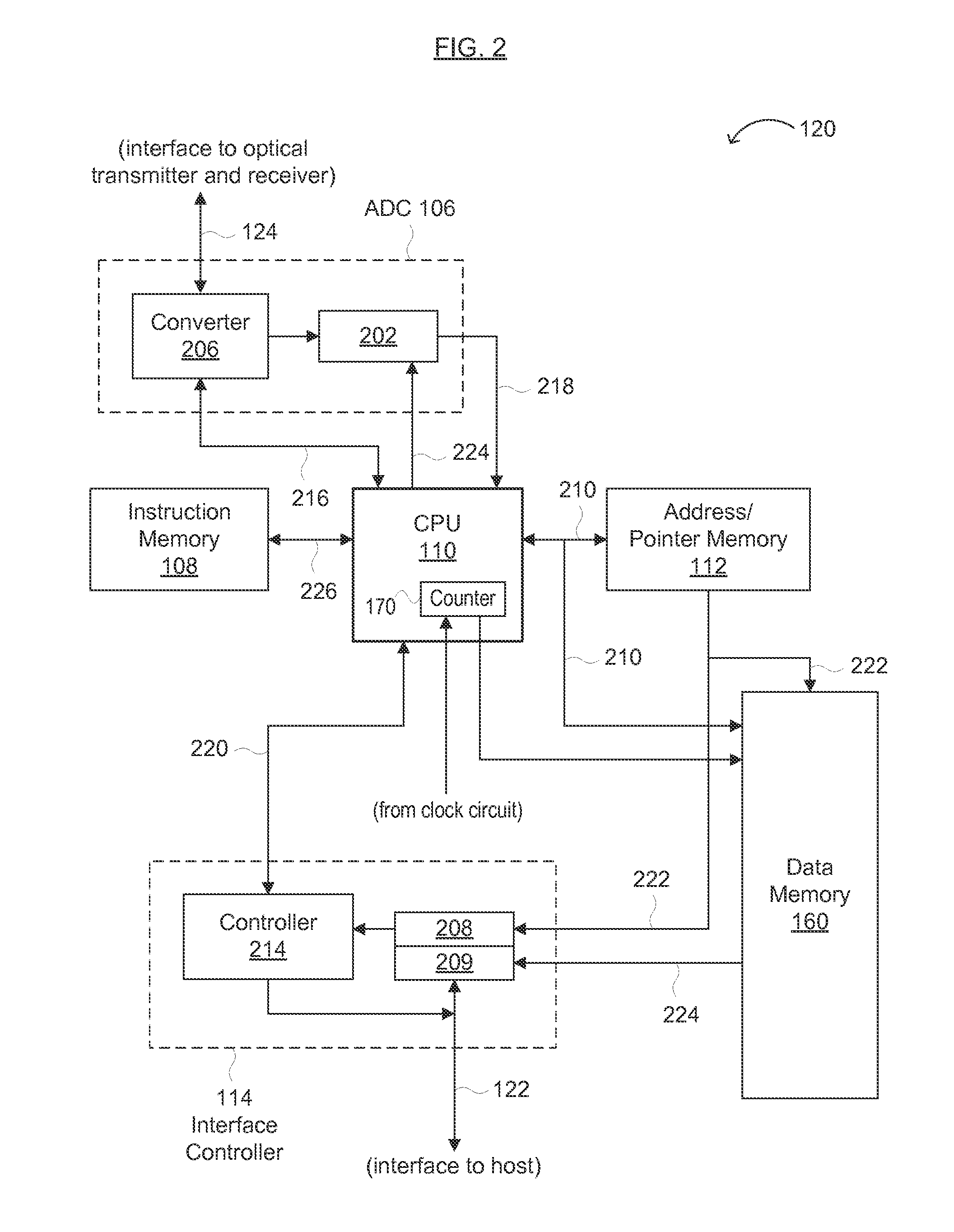
[0009]Embodiments of the present invention can advantageously provide an approach for monitoring an optical transceiver in real time, over a predetermined time interval, or over the entire operating life of the optical transceiver. A current value of a monitored operating parameter and an average operating parameter value (over a predefined time interval) can be stored and compared to predefined thresholds to determine whether components and / or circuitry in the optical transceiver are operating within an acceptable range. That is, the present invention can provide more accurate information regarding trends in optical transceiver operation, predict an impending transceiver failure, and be used as a type of “black box” to enhance failure analysis by providing details of the optical transceiver just prior to failure.

Problems solved by technology

However, conventional optical transceivers do not provide information regarding monitored parameters over time.

Method used


Image

  • Enhanced Status Monitoring, Storage and Reporting for Optical Transceivers
  • Enhanced Status Monitoring, Storage and Reporting for Optical Transceivers
  • Enhanced Status Monitoring, Storage and Reporting for Optical Transceivers

Examples


Embodiment Construction

[0016]Reference will now be made in detail to various embodiments of the invention, examples of which are illustrated in the accompanying drawings. While the invention will be described in conjunction with the following embodiments, it will be understood that the descriptions are not intended to limit the invention to these embodiments. On the contrary, the invention is intended to cover alternatives, modifications and equivalents that may be included within the spirit and scope of the invention as defined by the appended claims. Furthermore, in the following detailed description, numerous specific details are set forth in order to provide a thorough understanding of the present invention. However, it will be readily apparent to one skilled in the art that the present invention may be practiced without these specific details. In other instances, well-known methods, procedures, components, and circuits have not been described in detail so as not to unnecessarily obscure aspects of th...


PUM


Abstract

An optical transceiver and methods for using the same are disclosed. The optical transceiver and methods may be useful for providing more accurate information regarding trends in operation of the optical transceiver, predicting an impending failure of the optical transceiver, and providing details of the optical transceiver prior to failure. The optical transceiver generally includes (1) at least one of (i) a receiver configured to receive optical information and (ii) a transmitter configured to transmit optical information, (2) circuitry configured to sample data for one or more operational parameters of the receiver and/or transmitter, (3) logic configured to perform one or more statistical calculations on the sampled data to generate statistical information, and (iv) one or more memories configured to store the sampled data and the statistical information.

Description

FIELD OF THE INVENTION[0001]The present invention generally relates to the field of optical data communications and network technology. More specifically, embodiments of the present invention pertain to methods, algorithms, architectures, circuits, software, and / or systems for monitoring operational parameters in optical devices utilizing stored data and / or statistical analysis.DISCUSSION OF THE BACKGROUND[0002]Optical transceivers send and receive data in an optical form over an optical link, such as a fiber-optic link. An optical transmitter can include laser driver circuitry to drive a laser or diode, such as a light-emitting diode (LED), to create optical pulses on the fiber-optic link from received electronic signals. An optical receiver can include a photosensitive diode to receive optical signals, which are then converted into electronic signals. Thus, an optical transceiver converts (i) optical signals into analog and / or digital electronic signals, and (ii) electronic signal...

Claims


Application Information

Patent Timeline
Patent Type & Authority Applications(United States)
IPC IPC(8): H04B10/08
CPCH04B10/40H04B10/075
Inventor AZADEH, MOHAMMAD
Owner SOURCE PHOTONICS
Why Eureka
Try Eureka